




Custom Pinion Shaft Solutions for OEM Projects
Custom Shaft/pinion-shaft">pinion shaft projects seldom succeed using off-the-shelf specs, as OEM drivetrains generally carry larger, more repeated stresses than catalog parts are intended for. Heng Guan Bearing engineers pinion shaft components to precise specifications that provide reliable, repeatable outcomes for OEM teams on several projects. Understanding how the custom pinion shaft will really work inside the assembly is the first step to getting the right specification. Partnering with an experienced manufacturer makes it easier for engineering teams to source the component and get from print to completed part without surprises.
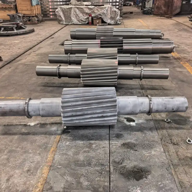
How Should OEMs Specify the Right Pinion Shaft for Custom Projects?
To figure out what a pinion shaft needs, you must first know how it will be used in the process. The direction of the load, the speed of rotation, the way the parts are mounted, and the expected duty cycle all affect the ideal shaft diameter, the spline pattern, and the bearing-seat sizes. There are a few important things you should think about before you start choosing designs: How many different types of torque can the pinion shaft transmit?
Will it have a lot of shocks or run in a steady stream? Does it have to be small, or is there room for a shaft with a bigger diameter? The engineering staff at LYHGB says that OEMs should look at these early on because fixing them early on saves them a lot of money on redesigns. This will often find problems with fit before they get to production. From the point of view of assembly in general, not just the picture.
| Specification Factor | What OEMs Should Confirm |
|---|---|
| Torque and Load | Maximum and average torque values |
| Speed | RPM range and duty cycle |
| Mounting | Bearing seat diameters and shoulders |
| Spline / Gear Mesh | Module, pressure angle, tooth count |
| Environment | Temperature, lubrication, exposure conditions |
Pinion Shaft Materials, Gear Geometry, and Heat Treatment Requirements
Material selection drives almost every downstream choice for a pinion shaft. Case-hardening steels such as 20CrMnTi and 42CrMo (or 40Cr) have a robust HRC 28-32 core with a wear-resistant HRC 58-62 carburized surface, and customer-specified alloys may be provided if corrosion or temperature requires. The gear geometry is just as important as the raw material: the module, the tooth profile, and the pressure angle influence how softly the pinion shaft meshes with its matching gear.
LYHGB offers spur, helical, and bevel tooth shapes in module M3–M20, with keyway, spline, flange, or entirely custom connections. Heat treatment closely follows geometry. Distortion during carburizing must be expected with careful fixturing and, if necessary, post-hardening grinding to bring crucial dimensions back to print.
| Parameter | Specification |
|---|---|
| Shaft Diameter / Length | φ50–500 mm (up to φ800 mm); 300–3,000 mm (up to 6,000 mm) |
| Base Material | 20CrMnTi, 42CrMo, 40Cr (customer-specified alloys accepted) |
| Case Hardness | HRC 58–62 (carburized tooth surface) |
| Core Hardness | HRC 28–32 (quenched and tempered) |
| Module / Tooth Profile | Module M3–M20; spur, helical, or bevel |
| Tooth Accuracy | GB 5–6 / ISO 1328 Class 6–7 |
What Pinion Shaft Tolerances and Quality Standards Should OEMs Require?
Tight tolerances are what separate a pinion shaft that performs consistently from one that generates premature wear or unwanted noise. Runout, concentricity, and surface finish on bearing journals typically need to stay within a few microns, while gear-tooth accuracy is often specified to AGMA 10–13 or DIN 5–7 grades, with LYHGB production aligning to GB 5–6 / ISO 1328 Class 6–7 for international OEM customers.
It is worth requesting full inspection documentation, including CMM tooth-geometry reports, ultrasonic flaw detection on forgings, and surface-and-core hardness gradient verification, rather than relying on a supplier's word alone. If your engineering team wants to review sample tolerance charts or quality documentation for a specific pinion shaft project, reaching out to mia@hgb-bearing.com is a straightforward way to get project-specific answers instead of generic brochures.
| Quality Aspect | Typical Requirement |
|---|---|
| Runout | ≤ 0.005–0.015 mm |
| Gear Accuracy | AGMA 10–13 / DIN 5–7 |
| Surface Finish | Ra 0.4–0.8 μm on journals |
| Case Hardness | 58–62 HRC to specified depth |
Custom Pinion Shaft Manufacturing and Precision Machining Options
At every step of the manufacturing process, it must be possible to track how a finished pinion shaft was made from a drawing. For fatigue strength and grain flow, a single-piece forged structure is used. The basic shape is made by close-tolerance precision machining. The teeth are cut with gear cutting, and the areas that are used are strengthened by carburizing. Precision grinding brings gear faces and bearing shafts back to the tolerances specified in the print.
Before being shipped, a CMM check is done to make sure the tooth geometry is correct. Because LYHGB does all of these things in-house, the wait time is shorter, and there are fewer mistakes when the pinion shaft is passed from one random supplier to another. OEMs that are making small batches of prototypes or larger quantities often need a single source that can increase production while keeping the same tolerances. This is what makes the difference between a smooth product launch and a delayed one. Early sample runs also let engineering teams make sure the fit is right before committing to full production tooling.
| Process Step | Purpose |
|---|---|
| Single-piece Forging | Establish grain flow for fatigue strength |
| Precision Machining | Shape base shaft geometry |
| Gear Cutting | Form spur, helical, or bevel teeth |
| Carburizing and Tempering | HRC 58–62 case / HRC 28–32 core |
| Precision Grinding | Restore journals and gear faces to print |
| CMM Tooth Inspection | Verify geometry and tolerance compliance |
Conclusion
Custom pinion shaft projects succeed when material, geometry, tolerances, and manufacturing process are treated as one connected decision, not separate line items. LYHGB's integrated approach helps OEMs move from specification to finished part with fewer surprises along the way.
FAQ
Q1: What lead time can OEMs expect for a custom pinion shaft?
A: For standard designs, lead time is roughly 4–6 weeks after drawing confirmation; complex or special-material orders typically take 8–10 weeks. Prototype batches are often shorter, so confirm timelines during quoting.
Q2: Can an existing pinion shaft drawing or sample be matched?
A: Yes. Reverse-engineering from a sample or partial print is possible when original documentation is not available.
Q3: What materials work best for high-load pinion shafts?
A: Case-hardening steels such as 20CrMnTi, 42CrMo, and 40Cr are common choices for demanding torque and wear conditions; customer-specified alloys are accepted for corrosion or high-temperature applications.
Q4: Are inspection reports included with each pinion shaft order?
A: Yes. Each shipment includes CMM tooth-geometry data, surface-and-core hardness gradient verification, ultrasonic flaw detection on forgings, material composition analysis, and magnetic particle inspection on critical areas.
Q5: Can small prototype batches be produced before full-scale manufacturing?
A: Yes. Low-volume prototype runs help validate fit and function before committing to production tooling.
Q6: What quality-system documentation ships with the order?
A: All orders are produced under ISO 9001:2015 quality management, with RoHS-compliant materials and full traceability for both raw-material certificates and finished-part inspection records.
Ready to Start Your Custom Pinion Shaft Project?
Have a pinion shaft drawing ready, or need help specifying one from scratch? Contact the LYHGB team at mia@hgb-bearing.com to discuss your OEM project. Whether it is a single prototype or a production run, we are ready to help you move forward with confidence.
References
1. American Gear Manufacturers Association (AGMA). ANSI/AGMA 2015-1-A01 — Gear Classification and Inspection Handbook.
2. ASM International. Heat Treater's Guide: Practices and Procedures for Irons and Steels (2nd ed.).
3. Society of Automotive Engineers (SAE). Materials and Processes for Automotive Drivetrain Components. SAE Technical Papers Series.
4. Dudley, D. W. Handbook of Practical Gear Design. McGraw-Hill.
5. International Organization for Standardization. ISO 1328-1:2013 — Cylindrical Gears — ISO System of Flank Tolerance Classification — Part 1: Definitions and Allowable Values of Deviations Relevant to Flanks of Gear Teeth.
6. American Society of Mechanical Engineers (ASME). ASME Y14.5-2018 — Dimensioning and Tolerancing.

WHAT OUR CUSTOMERS SAY
Here is the customer's evaluation of us
YOU MAY LIKE
 VIEW MORERKS.23.0941 Slewing Bearings
 VIEW MORERKS.22.0641 Slewing Bearings
 VIEW MORE161.40.2000.890.11.1503 Slewing Bearings
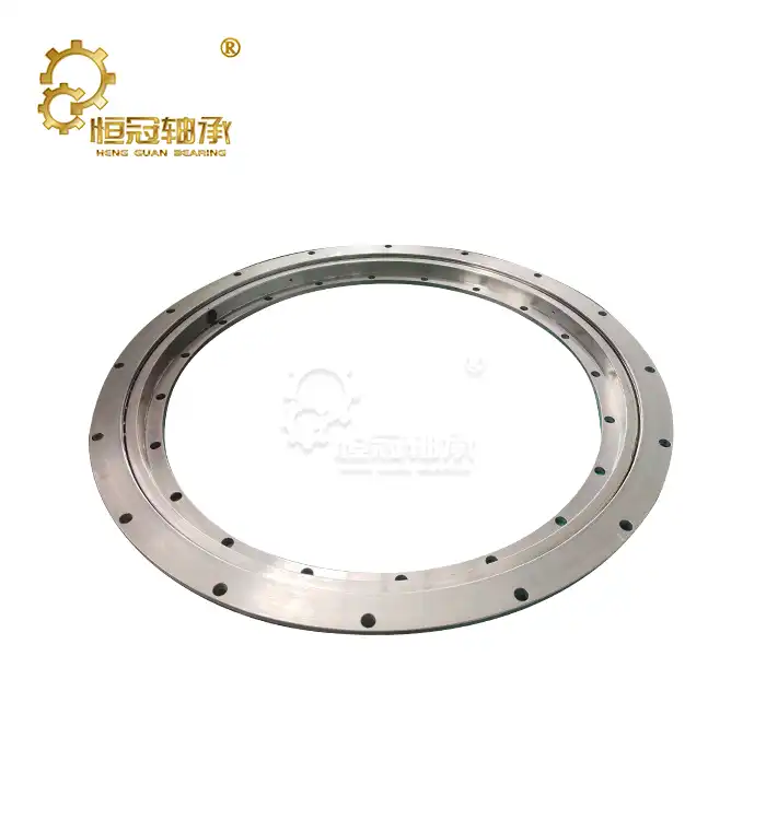 VIEW MORE020.30.900 Slewing Bearing
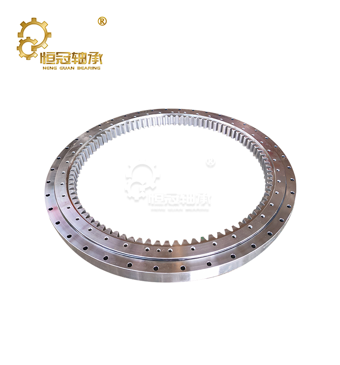 VIEW MOREDaewoo Excavator slewing bearing
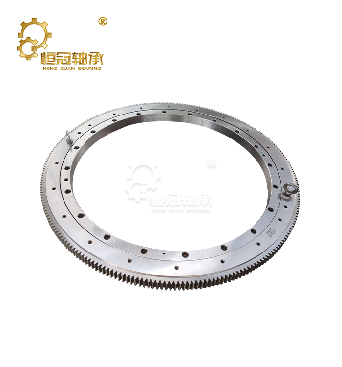 VIEW MORECross Roller Ring Bearing
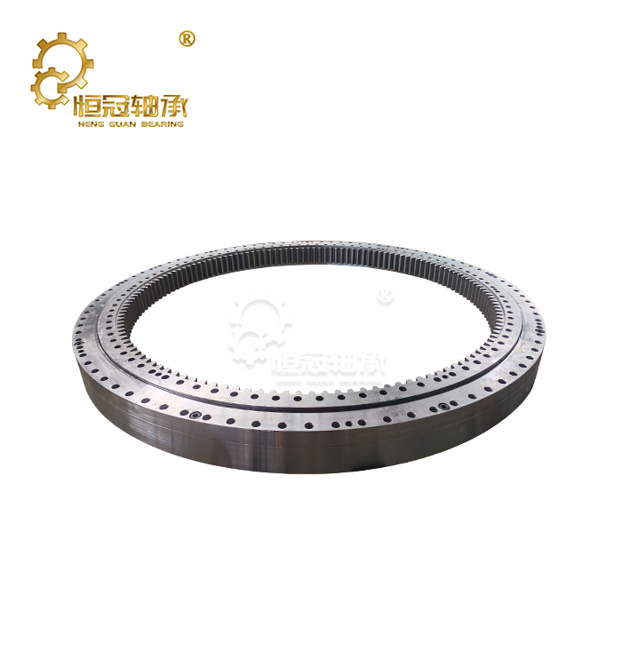 VIEW MORENK450B Swing Bearing
 VIEW MOREInternal Gear Rotary Slewing Bearing