



How Does Wind Turbine Slewing Bearing Improve Efficiency?
In a wind turbine, the moving parts limit the amount of energy it is able to harvest, and few have a bigger impact than the bearing that holds up the nacelle and the blades. Heng Guan Bearing designs and produces wind turbine slewing bearing assemblies that allow yaw and pitch systems to spin smoothly in continuously changing wind conditions. This article shows how this one component influences the entire turbine efficiency from wind tracking to long-term energy production, and why the nuances of its design are significantly more important than they seem.
How Does a Wind Turbine Slewing Bearing Improve Yaw and Pitch Control?
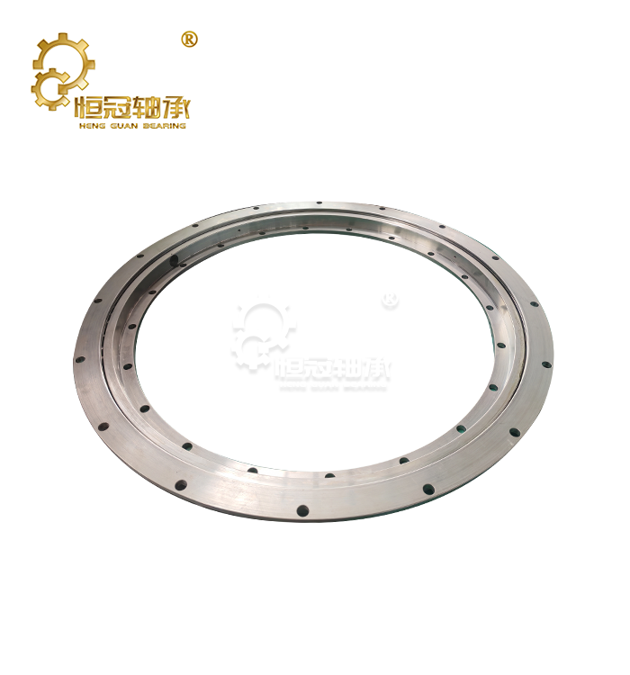
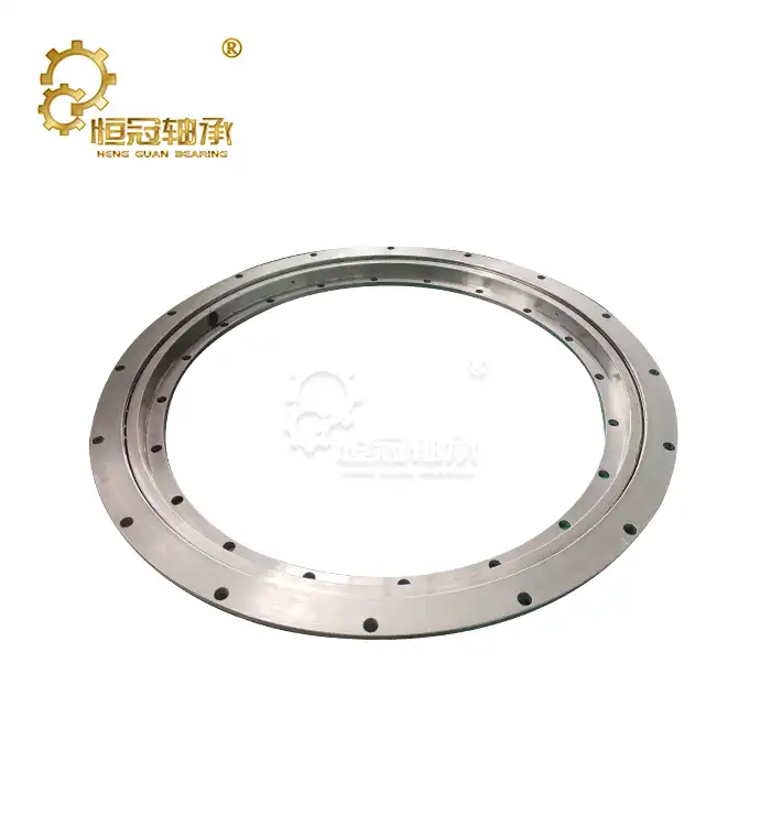
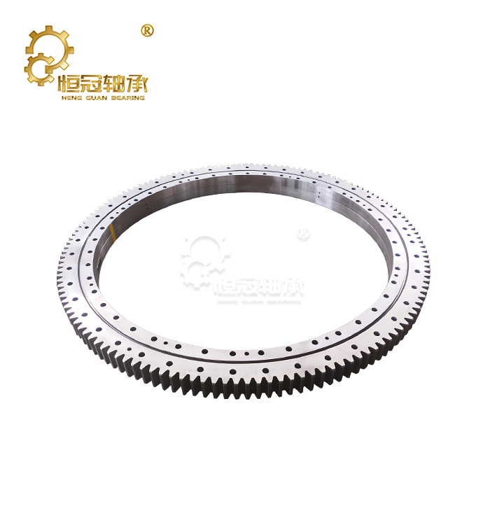
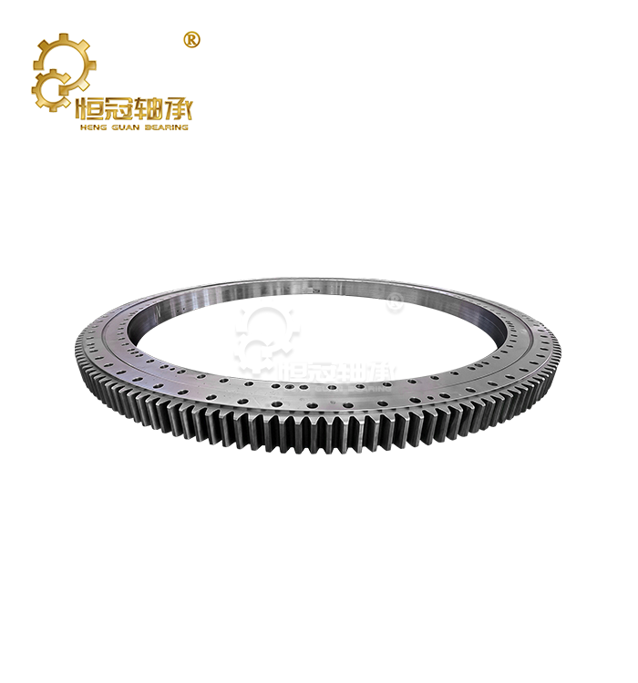
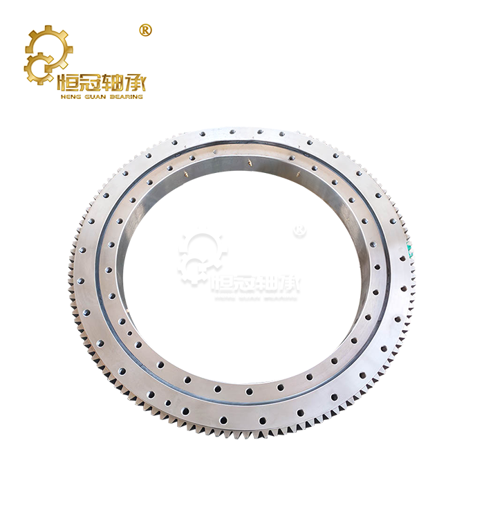
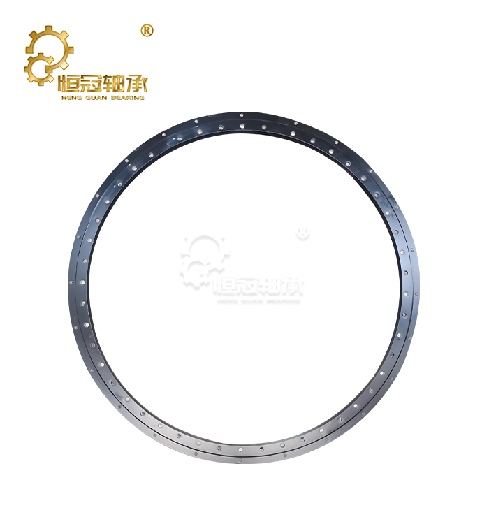
Yaw and pitch systems depend on smooth, accurate rotation to maintain the blades at the right angle and the nacelle toward the wind. Both have, in the middle, a wind turbine slewing bearing, which supports enormous rotational loads and provides precise, controlled movement when the direction of the wind changes. Even that little movement or stiffness in this bearing might cause a slow reaction to yaw and impair the ability of the rotor to keep aligned with the wind. Think about how many times the pitch changes in a day with changeable wind. A slewing bearing with tight raceway tolerances makes that continual change smooth, and not jerky, which improves control accuracy as well as downstream mechanical parts.
LYHGB maintains raceway tolerances to ±0.01 mm and vibration runout to less than 0.3 µm for consistent blade angle adjustments.
| Control Function | Role of the Slewing Bearing |
|---|---|
| Yaw Adjustment | Rotates nacelle to track wind direction |
| Pitch Adjustment | Rotates blade angle for optimal capture |
| Load Support | Carries axial, radial, and moment loads |
| Motion Smoothness | Reduces backlash during small corrections |
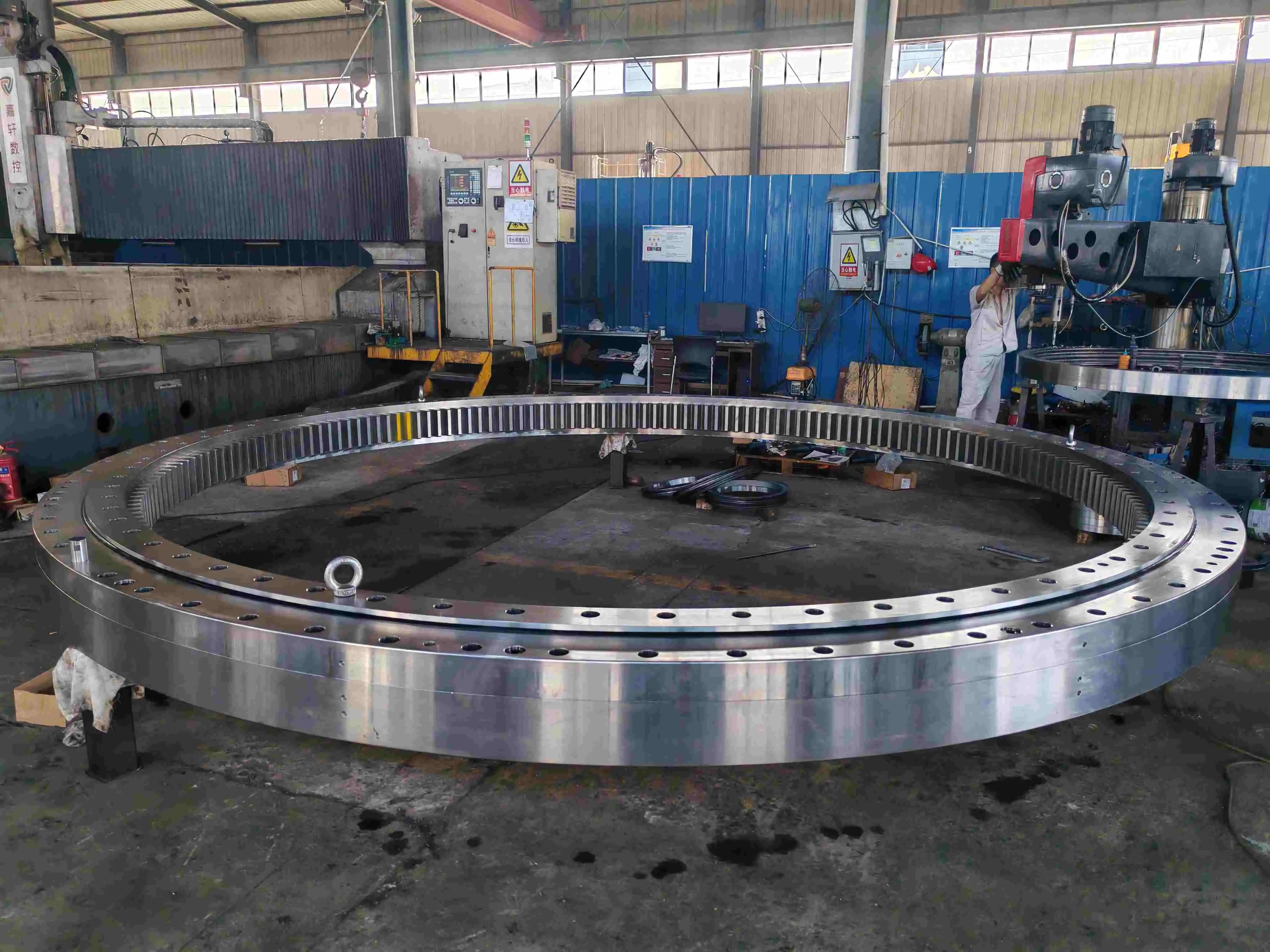
Wind Turbine Slewing Bearing Load Capacity and Energy Efficiency
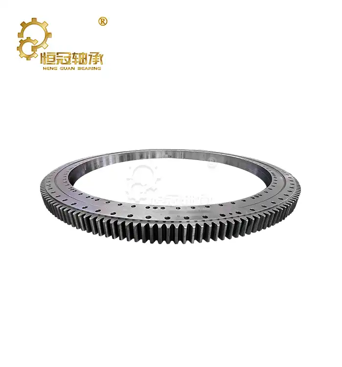
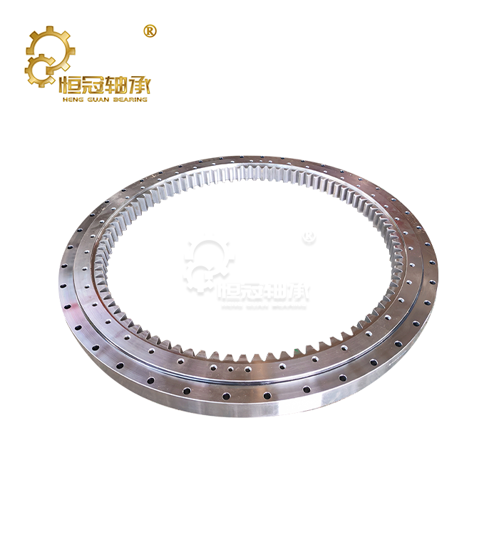
The load capacity is where a wind turbine slewing bearing earns its keep. The bearings are subjected to immense axial, radial, and moment forces due to rotor weight, wind thrust, and gravity, and must turn reliably for years without maintenance downtime. The LYHGB wind turbine slewing bearings have an inner diameter of 1,500 mm to 5,000 mm and an outer diameter of up to 5,500 mm with gear modules of M16 to M40.
Fatigue tests with more than one million load cycles at axial loads up to 3,000 kN and radial loads of up to 2,000 kN prove the performance of LYHGB slewing bearings. But undersized or poorly designed bearings not only risk early failure but also produce friction losses that silently chip away at the turbine’s net energy production over time. This matching of capacity to the application keeps parasitic losses low and allows the turbine to convert a greater percentage of the available wind to useful power during its working lifespan.
| Parameter | Specification |
|---|---|
| Inner / Outer Diameter | 1,500–5,000 mm / 1,800–5,500 mm |
| Height Range | 100–400 mm |
| Gear Module | M16–M40 |
| Axial Load Capacity | Up to 3,000 kN |
| Radial Load Capacity | Up to 2,000 kN |
| Design Life | 20+ years (per IEC 61400) |
Why Does Low-Friction Performance Matter for Wind Turbine Slewing Bearings?
Friction is one of the quieter efficiency drains in any wind turbine system, and a wind turbine slewing bearing that runs smoothly can meaningfully reduce the parasitic power needed to drive yaw and pitch motors. Lower friction means more net output available for the grid, with raceway finish, rolling-element geometry, and lubrication all playing a part. LYHGB pairs a precision raceway finish with NLGI Grade 2 lithium complex grease at a yearly or 500-hour relubrication interval, and optional pre-drilled grease channels can integrate the bearing into the turbine's central lubrication network for extended maintenance intervals.
If your project team wants friction-torque or lubrication data for a specific wind turbine slewing bearing configuration, reaching mia@hgb-bearing.com directly gets faster, project-specific answers than a generic catalog. Sealing also matters: imported NBR seals suit standard duty, while FKM seals resist salt spray and chemicals for offshore sites, with operating temperatures from -40 °C to +120 °C.
| Friction Factor | Efficiency Impact |
|---|---|
| Raceway Surface Finish | Reduces rolling resistance |
| Lubrication Type | Maintains low torque over time |
| Seal Design | Blocks contaminants without added drag |
| Ball/Roller Geometry | Balances load capacity and smoothness |
How Do Slewing Bearings Optimize Wind Tracking and Power Capture?
All of these design variables end up coming down to one thing: how effectively the turbine can follow the wind and harvest energy. A responsive, accurate wind turbine slew bearing allows the yaw mechanism to maintain the rotor correctly oriented, and accurate pitch control allows the turbine to adjust blade angle for varying wind speeds, preserving efficiency and equipment in gusts.
LYHGB produces these bearings to accuracy classes up to P4, with P0, P6, and P5 also available, giving the repeatable, low-tolerance movement OEMs want for consistent tracking across large turbine fleets. Better monitoring over a 20+ year design life translates into a noticeable improvement in lifetime energy output. Offshore alternatives are enhanced with chemical-nickel plating and 1,000-hour salt-spray-validated seals for the most demanding locations.
| Design / Certification Parameter | Specification |
|---|---|
| Accuracy Grades | P0, P6, P5, P4 |
| Raceway Tolerance | ±0.01 mm |
| Vibration Runout | Below 0.3 µm |
| Fatigue Test | Over 1,000,000 load cycles |
| Design Life | 20+ years per IEC 61400 |
| Offshore Salt-Spray Validation | 1,000 h |
Conclusion
A wind turbine slewing bearing simultaneously influences the yaw response, load management, friction, and tracking accuracy. LYHGB’s precision-manufactured bearings improve turbine operation to operate more smoothly and collect more useful wind energy during the life of the turbine.
FAQs
Q1: What accuracy grades are available for wind turbine slewing bearings?
A: LYHGB offers P0, P6, P5, and P4 grades. P4 supports the most precise, repeatable yaw and pitch movement, with LYHGB raceway tolerances held to ±0.01 mm and vibration runout kept below 0.3 µm.
Q2: Which structural types suit larger turbine loads?
A: Double-row reducing ball and three-row roller configurations are common for higher-capacity wind turbines. LYHGB also offers special anti-corrosion and low-temperature variants, plus sensor-integrated bearings for condition monitoring.
Q3: Does bearing friction really affect turbine energy output?
A: Yes. Lower friction reduces the parasitic power needed for yaw and pitch motors, improving net output. LYHGB validates low-friction performance with raceway tolerances of ±0.01 mm and vibration runout below 0.3 µm across its wind turbine slewing bearing range.
Q4: How is sealing handled on wind turbine slewing bearings?
A: Imported NBR seals suit standard duty, while FKM seals resist salt spray and chemicals for offshore sites. The operating temperature range is -40 °C to +120 °C, with NLGI Grade 2 lithium complex grease at a yearly or 500-hour interval.
Q5: Can bearing specifications be customized per turbine model?
A: Yes. Load capacity, structure type, dimensions, and gear module can be tailored to specific turbine designs, and reverse-engineering is available when no 3D drawing exists.
Q6: What design life and certifications come with LYHGB wind turbine bearings?
A: Design life exceeds 20 years per IEC 61400, validated by fatigue tests over one million load cycles. All bearings are produced under ISO 9001 quality management with RoHS compliance and full batch traceability from raw-material certificates to final inspection reports.
Ready to Improve Your Turbine's Efficiency?
Looking for a wind turbine slewing bearing built around your turbine's exact load and control requirements? Contact the LYHGB team at mia@hgb-bearing.com to discuss specifications, lead times, and technical documentation for your next project. Standard modifications ship in 8–10 weeks, and full custom builds with new tooling typically take 12–16 weeks after drawing approval.
References
1. American Bearing Manufacturers Association (ABMA). ANSI/ABMA STD 11 — Load Ratings and Fatigue Life for Roller Bearings.
2. International Electrotechnical Commission (IEC). IEC 61400-1:2019 — Wind Energy Generation Systems — Part 1: Design Requirements.
3. International Organization for Standardization. ISO 76:2006 — Rolling Bearings — Static Load Ratings.
4. Manwell, J. F., McGowan, J. G., & Rogers, A. L. Wind Energy Explained: Theory, Design and Application (2nd ed.). Wiley.
5. International Organization for Standardization. ISO 281:2007 — Rolling Bearings — Dynamic Load Ratings and Rating Life.
6. National Renewable Energy Laboratory (NREL). Wind Turbine Drivetrain Reliability Database Research Reports.

WHAT OUR CUSTOMERS SAY
Here is the customer's evaluation of us