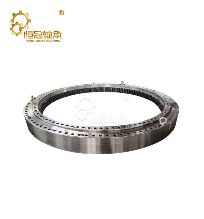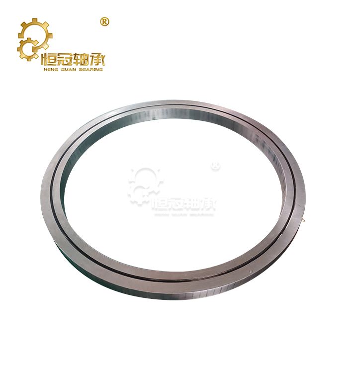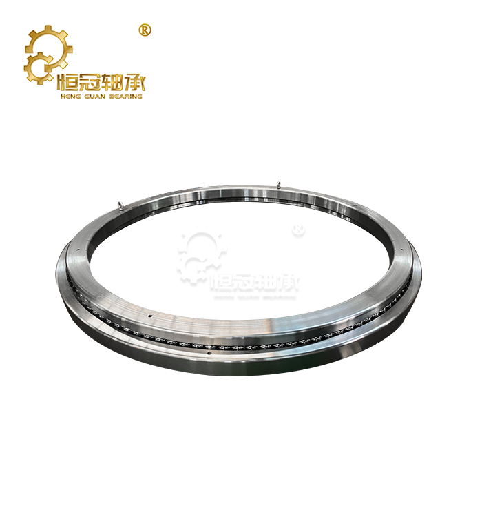




Crossed Roller Bearings Offer Many Benefits for Robotic Systems
Robotic joints must combine accuracy, rigidity, compact dimensions, and reliable load support within a limited installation space. A Crossed Roller Bearing is designed for this type of motion system with the cylindrical rollers placed orthogonally between the inner and outer rings. This configuration permits one bearing assembly to carry radial, axial and moment loads with an excellent degree of rotational precision. Cross-roller designs are frequently utilised in industrial robotics, machine tools, precision rotary stages, inspection equipment and other systems that demand stiffness and regulated rotating motion. The key advantage for robotic applications is not only a higher load capacity. A variety of load-support duties can be performed by the bearing within a single small package, which may simplify joint design and help engineers deal with limited space. However, real performance relies on bearing model, preload, size, lubrication, mounting precision and housing rigidity. Therefore, bearing selection should always be made on the basis of the full working conditions and not on a single performance statistic.
How do crossed roller bearings work in robotic joints?
Orthogonal Rollers Create Multi-Directional Load Support
In crossed roller bearings, cylindrical rollers are placed alternately at roughly 90° to each other. The rollers run in V-shaped raceways. The necessary distance apart for adjacent rollers is maintained by spacer cages or separators. The bearing can therefore accommodate radial and axial forces, as well as overturning moments due to the rollers' various orientations.
This setup is very beneficial in robotic joints. A robot arm does not always produce a straightforward radial load. The bearing can suffer a combination of radial force, axial force, and moment as the arm speeds up, slows down, or moves a tool away from the joint centerline. These loads can be supported by one bearing assembly instead of many bearing arrangements for different load directions. This is achieved using a crossing roller arrangement.
Load ratings are particular to the model. The basic dynamic and static load ratings and allowable moment or stiffness are usually available in manufacturer catalogs. For example, THK offers cross-roller models in varying load-rating ranges and structural designs, illustrating why engineers should choose a specific model instead of applying a single general load value to all crossed roller bearings.
Compact Construction Supports Space-Constrained Designs
Many robotic joints need to fit a motor, reducer, encoder, wires, brakes, and structural elements in a tiny envelope. The usage of many components in a bearing assembly might increase the joint diameter and axial length.
A crossed roller bearing can reduce the number of bearing components necessary to support combined loads. This may provide designers additional latitude in the layout of tiny robot joints or rotating mechanisms. The benefit is most relevant to articulated robots, precision positioning stages, semiconductor equipment, and inspection systems when mechanical space is limited.
But compact dimensions should not be addressed in isolation from the design of the housing. The stiffness of the bearing can depend on the accuracy and stiffness of the housing, flange, and mounting bolts. Therefore, the surrounding structure must be constructed to make use of the mechanical capabilities of the bearing.
Key Benefits for Robotic Motion Systems
High Rigidity for Stable Positioning
Positioning precision of robots is not only about encoder resolution. The mechanical deformation of the joint can cause inaccuracies between the commanded position and the actual end-effector position. So the stiffness of the bearing is an integral part of the whole mechanical system.
Crossed roller bearings are appreciated for their great stiffness thanks to the line contact between the rollers and the raceways. Their configuration is very suitable for applications where moment loads would otherwise produce significant angular displacements. THK points to high rigidity and rotation accuracy as features of their cross-roller ring products for industrial robots and precision machines.
For an OEM, this means that the bearing must be assessed combined with the housing and the support structure. A rigid bearing cannot compensate for a flexible housing or a flange that is not rigid enough. The whole mechanical assembly determines the ultimate positioning performance.
Accurate and Repeatable Rotary Motion
Many robots do the same motions thousands or millions of times. Small inaccuracies in rotational precision can add up to apparent positioning errors at the end effector, particularly if the robot arm is long or the joint is operating under a large payload.
A crossed roller bearing is employed in precision rotary applications because the roller configuration and controlled internal geometry can furnish accurate rotational guiding. For applications needing more precise motion control, high-precision versions are available. Besides regular series, THK provides specialized precision cross-roller products.
Engineers should not assume that a certain bearing grade inevitably implies a certain end-effector precision. Robot accuracy also depends on reducer backlash, encoder resolution, Shaft alignment, housing deformation, thermal expansion, control algorithms, and assembly tolerances. The bearing is one key part of the accuracy chain, not the sole portion.
Efficient Use of Installation Space
One of the most compelling reasons to adopt crossed roller bearings for robotic joints is they can handle several load directions in a single assembly. If the application permits, designers can use a compact cross-roller system instead of building a vast array of individual radial and thrust bearings.
This can simplify mechanical packaging and potentially minimize the number of interfaces that need to be aligned during assembly. Fewer components might also make inspection and maintenance easier.
The real space saving achieved relies on the competing bearing configuration. Angular-contact ball bearings are used if extremely high speed is the major concern; however, alternative roller bearing types may be better suited for certain load combinations. Crossed roller bearings are the most attractive choice when compactness, moment rigidity, and precision are more important than maximum speed.
Controlled Friction and Smooth Rotation
Friction on a robotic joint effects motor torque, energy consumption, heat generation, and smoothness of motion. The cross roller bearings with spacer cages are designed to keep roller spacing and rolling behavior under control.
However, the ultimate level of friction is a function of a number of variables, including preload, lubrication, seal design, rotational speed, load, and bearing size. Thus, it is impossible to assign one friction coefficient or one noise level to all crossed roller bearings.
Engineers may prioritize minimal running resistance if you have clean precision equipment. Sealing and contamination prevention may become more vital in dusty, chip-filled, coolant-rich or other contaminant-laden environments. The suitable configuration should be selected according to the actual operating environment of the robot.
How to Select a Crossed Roller Bearing for a Robot?
Start With the Complete Load Case
Bearing selection should begin with the actual load conditions rather than the nominal robot payload alone.
Engineers should identify:
- radial loads generated by the robot structure and payload;
- axial loads created by the mechanism and acceleration;
- overturning moments caused by offset loads;
- acceleration and deceleration forces;
- operating speed and duty cycle;
- expected service life;
- environmental temperature;
- contamination level;
- lubrication requirements; and
- mounting and housing constraints.
Moment loads deserve particular attention in articulated robotic joints. A payload positioned far from the bearing center can generate a substantial overturning moment even when the payload itself is relatively light.
The selected bearing should then be checked against the manufacturer's dynamic and static ratings, permissible moment, required life, and applicable safety factors. THK's selection guidance treats nominal life, static safety factor, permissible moment, permissible axial load, and moment rigidity as separate considerations.
Match Accuracy to the Robot's Actual Requirement
Not every robot needs the highest available precision class. Using an unnecessarily high-precision bearing can increase cost without improving the performance of the complete system.
High-precision bearings are more appropriate for applications such as the following:
- precision positioning equipment;
- optical or inspection systems;
- semiconductor manufacturing equipment;
- laboratory automation;
- machine-tool rotary axes; and
- robotic mechanisms with strict repeatability requirements.
For general material handling, welding, palletizing, or other applications, the appropriate accuracy level may be lower.
The important point is to define the required system accuracy first and then determine the bearing accuracy needed to support it. The bearing specification should be verified using the manufacturer's technical documentation rather than assuming that a P-grade or other designation corresponds to one universal runout value.
Check Bearing and Housing Compatibility
A bearing can only perform as intended when the surrounding components meet the required geometric and stiffness conditions. Engineers should review shaft or seat dimensions, flatness, roundness, shoulder geometry, mounting tolerances, bolt patterns, and housing rigidity.
This is particularly important for crossed roller bearings because their performance can be influenced by housing deformation and mounting conditions. THK's technical information explicitly notes that housing, presser flange, and bolt deformation should be considered when evaluating moment rigidity.
For a new robotic joint, it is therefore useful to review the bearing and housing as one assembly instead of selecting the bearing first and designing the surrounding structure later.
Crossed Roller Bearings Compared With Other Bearing Options
Crossed Rollers vs. Angular Contact Ball Bearings
Angular contact ball bearings are widely used in rotary machinery and can provide excellent high-speed performance. They are often arranged in matched pairs or other configurations when combined radial and axial support is required.
Crossed roller bearings become attractive when the application places greater emphasis on compactness, moment rigidity, and precision rotary motion. A single cross-roller assembly can support radial, axial, and moment loads in multiple directions, which can simplify the mechanical arrangement.
The choice should therefore be based on speed, load, rigidity, available space, preload, service life, and cost rather than assuming that one technology is universally better.
Crossed Rollers vs. Conventional Cylindrical Roller Bearings
Conventional cylindrical roller bearings are highly effective for applications dominated by radial loads. However, their ability to support axial and moment loads depends on the specific design and additional bearing arrangements.
Crossed roller bearings are different because their orthogonal roller arrangement allows a single assembly to accommodate multiple load directions. This makes them particularly useful in rotary joints where an offset payload creates a significant moment.
Crossed Rollers vs. Other Compact Rotary Bearings
Other bearing technologies may provide advantages in high-speed operation, extremely low friction, large-diameter applications, or specialized environmental conditions. Crossed roller bearing should therefore be selected when their combination of rigidity, compactness, rotational accuracy, and multi-directional load capacity matches the application.
A good procurement decision compares the complete bearing assembly and its mounting requirements rather than comparing only the purchase price of individual components.
Installation and Maintenance Considerations
Prepare the Mounting Surfaces Carefully
Precision bearings require proper installation. Dirt, burrs, poor flatness, or incorrect mounting forces can affect rotational accuracy and shorten service life.
Before installation, the mounting surfaces should be cleaned and inspected. The housing and shaft should be checked against the bearing manufacturer's dimensional and geometric requirements. The bearing should then be installed according to the manufacturer's specified procedure.
Fasteners should be tightened in the recommended sequence and to the specified torque. Engineers should not use a generic percentage of bolt proof load as a universal bearing installation rule because the correct torque depends on the bearing design, fastener specification, joint construction, and manufacturer instructions.
Use the correct lubricant and lubrication method.
Lubrication is essential for controlling friction and wear. The correct grease or oil depends on the bearing design, speed, temperature, load, seal arrangement, and operating environment.
Relubrication intervals should not be treated as a universal number such as 2,000 or 3,000 hours. A continuously operating robot in a clean factory may have very different requirements from a robot exposed to dust, coolant, elevated temperatures, or frequent acceleration.
A maintenance program should therefore follow the bearing manufacturer's recommendations and adjust them based on actual operating conditions.
Monitor Temperature, Noise, and Running Condition
Routine inspection can help identify developing problems before they result in unexpected downtime. Maintenance teams can monitor the following:
- operating temperature;
- abnormal noise or vibration;
- changes in running torque;
- grease leakage;
- seal condition;
- mounting bolt condition; and
- changes in rotational accuracy.
For robots operating continuously, condition monitoring can provide additional value. Temperature and vibration sensors can be integrated into the equipment to identify changes in bearing behavior over time.
Procurement and Customization for Robotic Applications
Provide Complete Technical Information
When requesting a quotation, OEMs should provide more than the required bore diameter. A useful RFQ should include:
- bearing type;
- required dimensions;
- radial and axial loads;
- moment load;
- rotational speed;
- operating temperature;
- required accuracy;
- preload requirements;
- lubrication requirements;
- environmental conditions;
- expected service life; and
- quantity and delivery schedule.
Providing this information allows the supplier to recommend an appropriate model instead of simply offering the closest standard size.
Evaluate Quality Control and Engineering Support
For precision robotic components, supplier evaluation should include more than price. Buyers should ask about material traceability, heat treatment, grinding accuracy, dimensional inspection, rotational accuracy testing, preload control, lubrication, packaging, and final inspection.
A capable supplier should also be able to review drawings and provide technical feedback before production. Sample approval can be particularly useful for new robotic joint designs because it allows the OEM to verify fit, rotation, preload, and system performance before committing to larger production quantities.
Consider Custom Designs for OEM Projects
Standard cross-roller models are suitable for many applications, but OEM equipment may require non-standard dimensions, mounting configurations, preload characteristics, or accuracy requirements.
Customized designs can be considered when the standard catalog cannot meet the mechanical envelope or load conditions. In these projects, the supplier and OEM engineering teams should confirm the bearing design, housing interface, load conditions, and inspection criteria before production.
Future Developments in Crossed Roller Bearing Technology
Higher Rigidity and Precision
Robotic systems continue to demand higher positioning accuracy while becoming smaller and lighter. Bearing manufacturers are therefore developing structures that improve rigidity without unnecessarily increasing the size or weight of the assembly.
The industry already includes high-rigidity cross-roller models designed specifically for industrial robots and precision rotary equipment.
More Compact Robotic Joint Designs
Collaborative robots, compact automation systems, and lightweight positioning mechanisms place strong demands on joint packaging. Bearings with compact cross-sections can help engineers reserve more internal space for motors, reducers, sensors, and wiring.
However, smaller dimensions must always be evaluated against load capacity, rigidity, life, and operating speed. Miniaturization should not come at the expense of the mechanical requirements of the joint.
Condition Monitoring and Predictive Maintenance
Sensor technology is becoming increasingly relevant to industrial equipment. Temperature and vibration monitoring can provide useful information about changes in bearing operating conditions.
When these measurements are connected to the robot's control or maintenance system, OEMs can move toward condition-based maintenance instead of relying only on fixed inspection schedules. This can be especially useful for production lines where unexpected joint downtime has a high operational cost.
Conclusion
Crossed roller bearing offer a strong combination of rotational accuracy, rigidity, compact construction, and multi-directional load support for robotic systems. Their orthogonal cylindrical roller arrangement allows one bearing assembly to accommodate radial, axial, and moment loads, making the design particularly useful for compact robotic joints and precision rotary mechanisms.
However, the best bearing is not determined by the keyword “precision” or by load capacity alone. Engineers should evaluate the complete load case, operating speed, required life, accuracy, preload, lubrication, housing stiffness, installation conditions, and environmental requirements. The selected model should then be verified against the manufacturer's technical data.
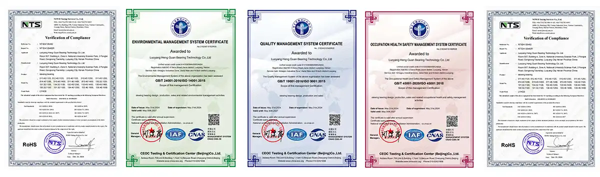
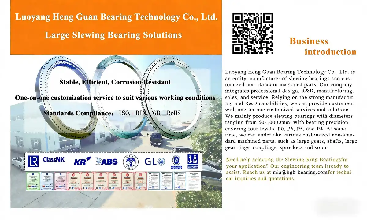
For OEM projects, working with a supplier that can support drawing review, customized bearing design, sample evaluation, dimensional inspection, and batch production can reduce selection risk and make integration easier. Luoyang Heng Guan Bearing Technology Co., Ltd. provides crossed roller bearing solutions for precision equipment and robotic applications, with support for customized dimensions and application-specific requirements. By reviewing the bearing and the surrounding mechanical structure together, robotics manufacturers can build joints that provide reliable rotary performance without sacrificing valuable installation space.
|
|
FAQ
1. What factors most significantly affect crossed roller bearing load capacity?
Load capacity is based on the width of the rollers, the number of rollers, the contact angle, and the qualities of the material. More rollers and bigger rollers spread forces over more contact spots, which increases capacity. V-shaped track angles are best for distributing load; 45-degree angles are common and balance radial and axial powers. The wear life under repeated loads is directly related to the hardness and finish of the material. In working conditions, the real load capacity is also affected by things like temperature, contamination, and the quality of the lubrication.
2. How do crossed roller bearings compare to angular contact bearings for robotic joints?
Crossed roller bearings are more rigid in the moment and take up less space when installed than dual angular contact bearing setups. The total load values of a single crossed roller unit are about the same as those of two angular contact bearings, but the system is 35–40% shorter. When used at high speeds, angular contact bearings are better, and the preload can be set more accurately by controlling the width of the spacers. The best bearing to use depends on the application's needs for space efficiency and speed capability.
3. Where can procurement teams source crossed roller bearings with OEM customization support?
For reliable sourcing, you need to work with well-known makers of Crossed Roller Bearings and approved dealers who can help you with technical issues. Global providers have engineering teams that can make things to order when the measurements or materials aren't standard or when there are special accuracy needs. Asking for samples to be looked at before placing an order reduces risks and makes sure that goods meet requirements. Building ties with multiple sellers in different parts of the world makes the supply chain more stable and lets you negotiate lower prices by buying in bulk.
Partner with Heng Guan for Your Precision Bearing Solutions
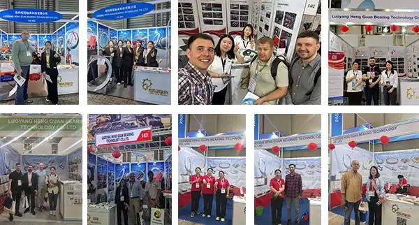
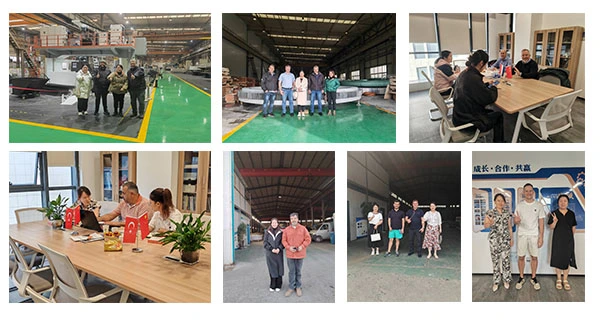
Luoyang Heng Guan Bearing Technology Co., Ltd. makes high-precision Crossed Roller Bearings that are designed to work with robotic systems that are very precise. Our wide range of products includes bore sizes from 50 mm to over 2000 mm and different levels of accuracy, such as P6, P5, P4, and P2, so you can find the right one for your needs. As a supplier of Crossed Roller Bearings with state-of-the-art production facilities in China's bearing manufacturing hub, we offer cost-effective options to original equipment makers (OEMs) and precision equipment manufacturers all over the world.
Our technical team offers individual optimization design services and works directly with your engineers to choose bearing setups that give you the best performance within the limits of your mechanical system. We are happy to take sample orders so that you can see how our products work before you commit to making a lot of them. Our experience exporting Crossed Roller Bearing products to Europe, the United States, and Asia makes the buying process go smoothly.Get in touch with our team at mia@hgb-bearing.com to talk about your unique needs and get full technical datasheets for our industrial robotics bearing solutions.
References
1. Harris, T.A. and Kotzalas, M.N. (2006). Advanced Concepts of Bearing Technology: Rolling Bearing Analysis, Fifth Edition. CRC Press, Boca Raton.
2. ISO 199:2014. Rolling bearings — Thrust bearings — Geometrical product specifications (GPS) and tolerance values. International Organization for Standardization, Geneva.
3. Weck, M. and Staimer, D. (2002). "Parallel Kinematic Machine Tools – Current State and Future Potentials." CIRP Annals - Manufacturing Technology, 51(2): 671-683.
4. Bompos, D.A., Artemiadis, P.K., Oikonomopoulos, A.S., and Kyriakopoulos, K.J. (2007). "Modeling, Full Identification and Control of the Mitsubishi PA-10 Robot Arm." Proceedings of the IEEE/ASME International Conference on Advanced Intelligent Mechatronics, Zurich, Switzerland.
5. Schaeffler Technologies AG & Co. KG. (2019). Rolling Bearings: Catalogue HR 1. Technical Publication, Herzogenaurach, Germany.
6. Park, J.H. and Lee, C.M. (2014). "A Study on the Precision Improvement of Robotic Machining by Stiffness Enhancement of Robotic Manipulator." International Journal of Precision Engineering and Manufacturing, 15(5): 845-851.

WHAT OUR CUSTOMERS SAY
Here is the customer's evaluation of us