




Can No Gear Slewing Bearings Handle Both Radial and Axial Loads?
Yes. A properly designed No Gear Slewing Bearing can carry radial and axial loads together, the actual capacity relies on the bearing configuration, rolling-element arrangement, raceway geometry, mounting structure, and the combined load imposed by the machine. The absence of an integrated gear does not automatically define what load a slewing bearing may handle. This distinction is significant in choosing a bearing for cranes, excavators, wind turbines, rotary tables, material handling equipment or other machinery that must revolve while sustaining a large structural load. Generally, the design of the slewing bearings is based on numerous load components such as radial force, axial force and overturning moment. For instance, SKF considers radial, axial, moment and torque loads as the principal resultant loads utilised in the evaluation of the slewing-bearing capacity. It’s for this reason why a No Gear Slewing Bearing is not just able to carry both radial and axial loads. The practical question is whether the selected bearing has enough capacity for the combined load case and operating circumstances of the application.
How a No-Gear Slewing Bearing Carries Combined Loads?
A no-gear slewing bearing is essentially a slewing-ring bearing without an integrated gear. The bearing itself can still contain inner and outer rings, rolling elements, raceways, cages or spacers, seals, lubrication paths, and mounting holes. The absence of gear teeth mainly affects how rotational drive is transmitted; it does not remove the bearing's ability to support external loads.
For many applications, the bearing is installed between a stationary structure and a rotating structure. The external forces pass through the mounting structure and bolt into the bearing rings, while the rolling elements transmit those forces between the raceways. This is why the supporting structure and bolt connection are part of the overall load-carrying system rather than secondary installation details. Technical guidance from Rothe Erde similarly treats load transmission through the bearing, companion structure, and mounting arrangement as part of slewing-bearing design.
Radial Load
Radial load acts approximately perpendicular to the bearing's rotational axis. Depending on the machine, it may come from the weight distribution of a rotating assembly, horizontal operating forces, material-handling forces, or external structural reactions.
The ability to carry radial load depends on the bearing's internal geometry and rolling-element arrangement. A bearing designed for high radial capacity may use cylindrical rollers or another configuration that provides greater radial load support than a lightweight ball-bearing arrangement.
The important point is that radial capacity should not be judged from the bearing's outside diameter alone. Two bearings with similar external dimensions can have different internal geometries and therefore different load ratings.
Axial Load
Axial load acts approximately parallel to the rotational axis. In a crane, for example, the vertical force generated by the supported structure can create a substantial axial component. Wind turbines, lifting systems, rotary platforms, and material-handling machinery can also produce significant axial loads.
Four-point contact ball slewing bearings are one example of a configuration that can support axial loads in both directions as well as radial loads and tilting moments. Rothe Erde describes four-point bearings as suitable for transmitting axial and radial loads and tilting moments.
However, the magnitude and direction of the load still matter. A bearing should be evaluated using the manufacturer's load-rating method or application-specific calculation rather than assuming that every four-point or gearless bearing has the same combined-load capability.
Overturning Moment Must Also Be Considered
Radial and axial loads are only part of the calculation for many slewing applications. A load positioned away from the bearing center creates an overturning moment.
For example, a crane may have a relatively moderate vertical load but a large moment because the load is positioned far from the slewing axis. The same principle applies to excavator booms, wind-turbine nacelles, and other structures with large offsets.
This is why a proper bearing selection normally considers at least the following:
axial load;
radial load;
overturning moment;
rotation speed;
duty cycle;
operating temperature;
mounting stiffness;
bolt arrangement; and
expected service life.
A bearing that appears adequate based on axial and radial loads alone may not be adequate once the overturning moment is included.
Which No-Gear Slewing Bearing Configuration Is Suitable?
Not every gearless slewing bearing has the same load distribution characteristics. The number of rolling-element rows and the type of rolling elements have a direct influence on the application range.
Single-Row Four-Point Contact Ball Bearings
Single-row four-point contact ball bearings are often selected when designers need a relatively compact bearing that can accommodate combined loads and moments.
The four-point contact geometry allows the balls to interact with the raceways in a way that supports axial and radial loading. These bearings can be attractive where space, weight, friction, and cost need to be balanced.
They are commonly considered for applications such as rotary tables, positioning equipment, smaller cranes, aerial work platforms, and other machinery where the combined load is within the bearing's calculated limits.
However, a four-point bearing should not automatically be described as the best choice for heavy-duty applications. If the machine produces very high radial loads, large axial loads, or severe overturning moments, a roller-based design may provide a more appropriate load-carrying arrangement.
Double-Row Ball or Roller Designs
Double-row configurations provide additional rolling-element capacity and can be selected when the application requires greater load support than a single-row design can provide.
Depending on the design, double-row cylindrical roller slewing bearings can accommodate substantial axial and radial loads as well as tilting moments. SKF lists double-row cylindrical roller slewing bearings among its configurations for heavy axial and radial loads and high tilting moments.
This makes double-row designs useful when the machine requires a stronger load-bearing system without immediately moving to a three-row arrangement.
Three-Row Roller Slewing Bearings
For very high-load applications, three-row roller designs provide a different approach. The three roller rows can be arranged so that separate raceways primarily support different load components.
A typical three-row arrangement uses two groups of rollers for axial and overturning loads and another group for radial loading. This allows the bearing geometry to be optimized for each major load direction. Technical references describe three-row roller bearings as configurations used for very high loads, with separate roller rows for axial and radial loading.
This design is particularly relevant to heavy machinery such as large excavators, mining equipment, ship loaders, cranes, and other systems where stiffness and load capacity are major design requirements.
Does No Gear Mean Higher Load Capacity?
One of the biggest problems in the original explanation is treating the lack of gear teeth as a direct reason for higher load capacity. A gearless design can provide valuable structural and maintenance advantages, but load capacity is determined by the complete bearing design.
A geared slewing bearing incorporates gear teeth into one of the bearing rings so that a pinion can drive the rotating structure. A no gear slewing bearing does not contain this integral drive gear and therefore requires a separate rotational drive arrangement when powered rotation is necessary.
The absence of teeth can simplify the bearing ring and remove the need to inspect and lubricate an integral gear mesh. But it does not mean that every gearless bearing has a greater raceway capacity than every geared bearing.
What Actually Determines Bearing Capacity?
The following factors are more important when comparing two bearings:
rolling-element size and number;
raceway diameter;
raceway profile;
contact angle;
internal clearance or preload;
ring cross-section;
material and heat treatment;
bearing arrangement;
mounting stiffness;
bolt connection;
lubrication;
operating temperature;
load spectrum; and
required service life.
The same general principle is reflected in major slewing-bearing manufacturers' technical information: bearing selection is based on the actual load combination and application conditions rather than simply on whether the bearing has a gear.
How to Select a No-Gear Slewing Bearing for Combined Loads?
Selecting the bearing should start with the machine rather than the catalog.
Start With the Complete Load Case
The engineering team should determine the maximum and normal values for axial force, radial force, and overturning moment. It is also important to identify whether these loads occur simultaneously or at different points in the operating cycle.
For example, an excavator may experience a different load combination while digging, lifting, swinging, and dumping. A crane may experience different combinations during lifting, slewing, braking, and holding.
The bearing therefore needs to be evaluated against the actual load spectrum rather than a single nominal load.
Check the mounting structure.
Even a correctly rated bearing can perform poorly if the supporting structure is too flexible or uneven.
The mounting surfaces should provide adequate stiffness and appropriate flatness. Bolt quantity, bolt grade, preload, hole pattern, and tightening procedure also matter because the external load is transmitted through the bearing connection.
This is particularly important for large slewing bearings. The bearing and its companion structure should be treated as one load-transmission system.
Consider Rotation and Duty Cycle.
Load capacity is not the only consideration. Rotation speed and operating frequency can influence friction, lubrication requirements, heat generation, and service life.
A bearing used for occasional positioning may have very different requirements from one that rotates continuously. Similarly, frequent start-stop cycles can produce different stresses from steady rotation.
Therefore, procurement specifications should include:
normal rotation speed;
maximum rotation speed;
operating hours;
start-stop frequency;
oscillating or continuous rotation;
load frequency;
shock or impact conditions; and
expected service life.
Lubrication and Sealing Affect Long-Term Load Performance
A bearing's rated capacity does not guarantee reliable performance if lubrication and contamination control are neglected.
Select Lubricant for the Operating Conditions
The lubricant must maintain an appropriate film between the rolling elements and raceways while remaining compatible with the bearing's seals and operating temperature.
The correct grease depends on the bearing design and application. Instead of applying a universal statement such as “NLGI 2 is always suitable,” the bearing manufacturer's lubrication recommendation should be followed.
For machines exposed to dust, water, abrasive particles, or high temperatures, lubrication intervals may need to be adjusted. Contamination can damage raceway surfaces and rolling elements even when the nominal mechanical load remains within the calculated limit.
Protect the Raceway From Contamination
Seals are particularly important in mining, construction, marine, and outdoor applications.
Dust, water, mud, metal particles, and other contaminants can enter the bearing if sealing is inadequate. Once contamination reaches the raceway, it can accelerate surface damage and increase operating torque.
The appropriate seal material and sealing configuration should therefore be selected according to temperature, chemicals, moisture, and contamination exposure rather than simply choosing the standard seal for every application.
Maintenance Checks for Gearless Slewing Bearings
Regular inspection of No Gear Slewing Bearing can help identify changes before they develop into major mechanical problems.
Monitor Rotation Torque and Operating Condition
Changes in rotation resistance can indicate problems such as lubrication deterioration, contamination, raceway damage, seal problems, or abnormal loading.
However, a fixed threshold such as “20% above the original torque always means the bearing must be replaced” should not be presented as a universal engineering rule. Torque should be evaluated against the manufacturer's specifications and the machine's normal operating baseline.
Temperature and vibration can also provide useful condition information when appropriate monitoring equipment is available.
Inspect Bolts and Mounting Surfaces
Mounting bolts should be checked according to the equipment manufacturer's maintenance procedure. Loss of preload can affect load distribution and may create abnormal stress in the bearing and surrounding structure.
For large or safety-critical machinery, bolt tension verification may require calibrated torque procedures, hydraulic tensioning, ultrasonic measurement, or another approved method.
Where Are No-Gear Slewing Bearings Used?
Because a no-gear slewing bearing separates the bearing function from the integral gear-drive function, it can be considered for applications where the designer has another suitable way to generate rotation.
Typical applications can include the following:
rotary tables;
material-handling equipment;
construction machinery;
mining equipment;
solar tracking systems;
wind-turbine systems;
industrial positioning equipment;
packaging machinery; and
specialized rotating platforms.
The appropriate configuration depends on the load combination. Four-point ball bearings can be suitable for compact combined-load applications, while roller configurations can be more appropriate where high radial loads, axial loads, or overturning moments dominate. Slewing-bearing manufacturers also list cranes, excavators, mining equipment, wind turbines, and antennas among applications for various roller and ball configurations.
What Information Should You Give the Manufacturer?
For a customized no-gear slewing bearing, providing only the required outside diameter is usually not enough.
A manufacturer should ideally receive the following information:
Maximum axial load — including both directions if applicable.
Maximum radial load — including the direction and whether it is constant or variable.
Maximum overturning moment — preferably at the bearing center.
Load combinations — showing which loads occur simultaneously.
Rotation speed — including maximum speed.
Duty cycle — continuous, intermittent, oscillating, or indexing.
Mounting dimensions — inner and outer diameter, height, bolt-circle dimensions, and hole pattern.
Operating environment — dust, water, salt spray, chemicals, temperature, and other contaminants.
Lubrication requirements — grease type and relubrication method where specified.
Expected service life — operating hours or number of cycles.
Installation orientation — especially for applications with unusual mounting conditions.
Drive arrangement — because a gearless bearing requires an external mechanism when powered rotation is needed.
With these parameters, the supplier can determine whether a single-row ball, double-row ball or roller, three-row roller, or another configuration is appropriate.
Why Manufacturer Verification Matters?
For industrial procurement, a bearing catalog should be treated as the starting point rather than the final design approval.
A qualified manufacturer should be able to provide dimensional drawings, material information, load ratings, recommended mounting conditions, lubrication requirements, inspection documentation, and application-specific engineering support.
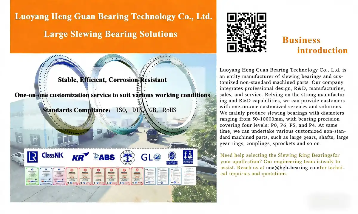
Luoyang Heng Guan Bearing Technology states that it manufactures slewing bearings and customized non-standard machining components and operates under an ISO 9001-certified quality system. For a specific project, however, buyers should still request the documentation applicable to the exact bearing model and configuration rather than relying on general company-level claims.
This is especially important for large bearings used in cranes, mining machinery, wind turbines, and other equipment where bearing failure can create significant downtime or safety risks.
Conclusion
A properly designed no gear slewing bearing can handle both radial and axial loads, and certain configurations can also accommodate substantial overturning moments. The key point is that gearless construction describes the absence of an integral gear drive; it does not, by itself, determine the bearing's load capacity.
Single-row four-point contact ball bearings can provide a compact solution for combined loading, while double-row and three-row roller configurations can be considered when higher radial, axial, or moment capacity is required. The appropriate choice depends on the complete load case, bearing geometry, rolling-element arrangement, mounting structure, lubrication, operating conditions, and required service life. Technical sources confirm that slewing-bearing selection needs to account for axial and radial forces together with tilting moments rather than evaluating one load direction in isolation.
For procurement, the safest approach is to provide the manufacturer with the actual axial load, radial load, overturning moment, speed, duty cycle, mounting dimensions, environmental conditions, and service-life requirements. With those inputs, a qualified bearing manufacturer can determine whether a particular no-gear slewing bearing is suitable and recommend the appropriate structural configuration instead of relying on a generic load-capacity claim.
|
|
FAQ
1. Can gearless slewing bearings really handle combined radial and axial loads effectively?
These bearings are designed to handle multiple loads in more than one direction. They do this by using the best raceway contact angles and rolling element setups. When chosen correctly for the job, the four-point contact design and cross-roller configurations spread pressures across many load paths, reaching rated capacities in both radial and axial directions.
2. How do I determine the appropriate bearing size and type for my load conditions?
Find the maximum radial forces by looking at the weight of the equipment and its working loads. Then, find the maximum axial forces by looking at thrust, wind, or process pressures. Use duty cycle factors that show whether the process is ongoing or intermittent. With this information, you can contact makers like Heng Guan to get help choosing bearings by using equivalent load estimates that are specific to each type of configuration.
3. What maintenance practices extend bearing life under heavy loading?
Schedule lubrication and use the right type of grease and intervals based on the speed of movement and the surroundings. Keep an eye on the spinning force to spot problems early. Check the tightness of the fixing bolts on a regular basis to keep the load evenly distributed. Check seals often to keep dirt and other things from getting in and speeding up wear when they're under load.
4. How does bearing accuracy grade affect load capacity?
Higher precision grades, such as P4 and P5, have tighter physical limits that make the spread of load more even and lower stress concentrations. Even though the estimated load capacity is the same for all grades, precision bearings work better and last longer when they are continuously loaded with heavy loads because they are made with higher-quality materials.
Partner with a Trusted No Gear Slewing Bearing Manufacturer
Luoyang Heng Guan Bearing Technology offers complete options for your rotating uses that have a lot of load. We can make things with widths from 50 mm to 10 m and with accuracy levels up to P4. We use high-tech materials like 42CrMo alloy steel and GCr15SiMn bearing steel to back this up. We make sure that the mounting configurations, seal types, and raceway geometries are exactly what you want. We also offer technical help throughout the specification development and operating life of the products. Our goods have been used by clients around the world in fields like construction, mining, wind power, and medical tools, and they have been shown to work well in tough conditions. Get in touch with our technical team at mia@hgb-bearing.com to talk about your needs and find out how our No Gear Slewing Bearing options can help your tools work better and last longer.
References
1. Harris, T.A. & Kotzalas, M.N. "Advanced Concepts of Bearing Technology: Rolling Bearing Analysis, Fifth Edition." CRC Press, Taylor & Francis Group, 2006.
2. Glodež, S., Potočnik, R. & Flašker, J. "Computational Model for Calculation of Static Capacity of Large Three-Row Roller Slewing Bearings." Journal of Mechanical Engineering Science, Vol. 227, Issue 12, 2013.
3. Aguirrebeitia, J., Abasolo, M., Vallejo, J. & Ansola, R. "General Static Load-Carrying Capacity of Four-Contact-Point Slewing Bearings for Wind Turbine Generator Actuation Systems." Wind Energy Journal, Vol. 16, Issue 5, 2013.
4. Zupan, S. & Prebil, I. "Carrying Angle and Carrying Capacity of a Large Single Row Ball Bearing as a Function of Geometry Parameters of the Rolling Contact and the Supporting Structure Stiffness." Mechanism and Machine Theory, Vol. 36, Issue 10, 2001.
5. Kania, L. "Modelling of Rollers in Calculation of Slewing Bearing with the Use of Finite Elements." Mechanism and Machine Theory, Vol. 41, Issue 11, 2006.
6. Zhou, J. & Chen, T. "Load Distribution Characteristics of Ball Bearings with Raceway Waviness." Tribology Transactions, Vol. 58, Issue 3, American Society of Mechanical Engineers, 2015.

WHAT OUR CUSTOMERS SAY
Here is the customer's evaluation of us