

Slewing Gear Load Capacity: Key Factors Explained
Understanding slewing gear load capacity represents a critical decision point for engineers and procurement professionals managing heavy machinery operations. The weight that a slewing gear can hold directly impacts how safe it is, how well it rotates, how long it lasts, and how often it needs to be serviced in heavy-duty situations. Picking the right load capacity is important for all kinds of machinery, from construction and mining tools to port cranes and industrial systems. It makes sure that the gear mechanism can handle constant use, shock loads, and changing working conditions. Checking a single grade number is not enough to figure out the slewing gear load capacity. Engineers have to think about many things, like the type of load, the design of the gears, the power of the materials, the working surroundings, the greasing conditions, and the expected service cycles. If you choose the right slewing gear, it will keep the rotation accurate, cut down on premature wear, and make the whole piece of equipment more reliable. When picking slewing gear options for tough jobs, equipment makers, engineers, and buying teams can make better choices when they know about these factors.

How Slewing Gear Load Capacity Is Determined
What Does Slewing Gear Load Capacity Mean?
The slewing gear load capacity is the maximum weight that a gear and bearing system can safely hold while still working properly and lasting as long as it's supposed to. Usually, these loads are made up of axial loads, radial loads, and rotating moment loads. In real life, these loads work together. The highest load that a fixed slewing gear system can hold without permanently deforming important parts is called its static load capacity. Dynamic load capacity takes into account effects like fatigue that happen while equipment is being used, constant rotation, and repeated loading cycles. Because most industrial equipment works with changing loads instead of a constant load, dynamic conditions often determine how well it does its job in real life. For instance, cranes, loaders, and lifting systems speed up, slow down, and change directions a lot, which puts extra stress on the gear structure.
Load capacity is commonly expressed through:
- Axial load rating — the vertical force supported along the rotation axis.
- Radial load rating — the side force acting perpendicular to the rotation axis.
- Moment load rating — the overturning force created by distance between the applied load and the rotation center.
Among these factors, moment load is often the most critical consideration because even a moderate external force can create a large overturning effect when applied at a long distance from the bearing center.
Main Types of Loads Acting on Slewing Gear Systems
Different equipment creates different loading conditions. Understanding each load type is essential for selecting a suitable slewing gear design.
Axial Load
Axial loads act parallel to the rotation axis and are commonly generated by vertical forces.
Typical examples include:
- The weight of lifting equipment components
- Suspended loads in cranes
- The upper structure weight of excavators
In these applications, the load is transferred through rolling elements and raceways. Proper load distribution prevents excessive contact stress and extends operating life. For heavy lifting equipment, insufficient axial capacity may cause raceway deformation, uneven wear, and reduced positioning accuracy.
Radial Load
Radial loads act perpendicular to the rotation axis. They usually occur because of side forces, external pressure, or operational movement.
Common sources include:
- Wind forces acting on crane structures
- Side digging forces on excavators
- Horizontal movement loads in industrial machinery
Radial loads influence gear alignment and contact conditions between components. When excessive radial forces occur, uneven tooth contact may develop, accelerating wear and reducing transmission efficiency.
Moment Load
Moment load represents a tilting force around the rotation center. It is calculated based on the relationship between applied force and distance:
Moment Load = Force × Distance
This explains why equipment with a long boom or extended working arm creates higher loading demands even when the actual lifted weight remains unchanged.
For example, a crane lifting a load far from the rotation center produces a much larger overturning moment than lifting the same load close to the base.
Because of this effect, moment load evaluation is especially important for:
- Mobile cranes
- Excavators
- Offshore equipment
- Port handling machinery
Combined Loading Conditions in Real Applications
In real operating environments, slewing gear systems rarely experience only one type of load. Axial, radial, and moment loads usually occur simultaneously.
For example, an excavator working with a fully extended boom may experience:
- Axial load from the upper structure weight
- Radial load from digging resistance
- Moment load from the extended bucket position
Engineers must evaluate these combined conditions rather than relying only on individual load ratings.
A reliable load capacity assessment considers:
- Maximum operating load
- Frequency of load changes
- Shock impact conditions
- Rotation speed
- Expected service life
Understanding Slewing Gear Load Rating Standards
Static and Dynamic Load Rating Evaluation
Load ratings provide a standardized method for comparing different slewing gear solutions. However, rating values should always be evaluated together with actual operating conditions.
Static ratings focus on preventing permanent deformation under maximum loads, while dynamic ratings consider fatigue resistance during repeated rotation.
For example:
- A positioning system operating occasionally may prioritize static strength.
- A continuously rotating crane system requires stronger fatigue performance.
Selecting a gear based only on maximum static capacity may result in reduced service life if the application involves frequent movement cycles.
Safety Factors in Slewing Gear Selection
Safety factors provide additional capacity margins between theoretical ratings and actual operating conditions.
The required safety factor depends on:
- Load stability
- Shock impact frequency
- Environmental conditions
- Maintenance quality
- Equipment importance
Heavy-duty applications such as mining machines and port cranes often require higher safety margins because unexpected loads, vibration, and harsh environments can increase actual stress levels.
In practical engineering projects, manufacturers typically analyze operating conditions rather than applying a fixed safety factor to every application.
Why Load Rating Standards Matter
International standards help manufacturers and users evaluate performance consistently.
Commonly referenced standards include:
- ISO bearing calculation methods
- DIN industrial bearing specifications
- Application-specific lifting equipment requirements
These standards provide guidance for:
- Load calculation methods
- Fatigue life evaluation
- Testing procedures
- Documentation requirements
However, standards alone cannot replace engineering analysis. The final slewing gear selection should always consider the actual machine structure and working environment.

Critical Design Factors Affecting Slewing Gear Load Capacity
Bearing Configuration and Structural Design
The way a slewing gear system is built on the inside affects how it distributes load, how accurately it rotates, and how long it lasts in service. Different structure designs are chosen based on the needs of the equipment, the space that can be used for placement, and the estimated loads.
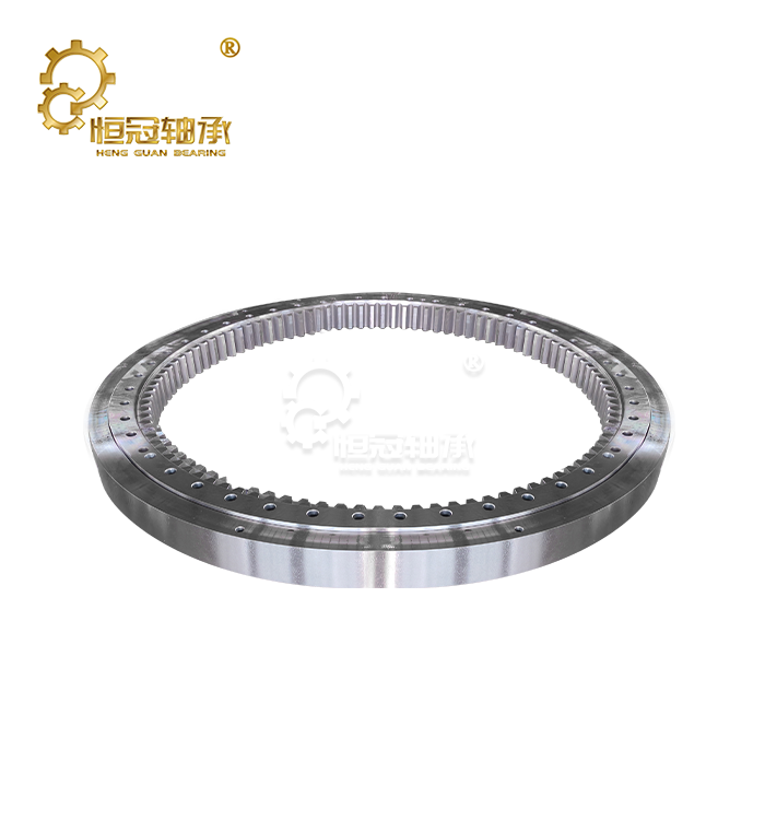
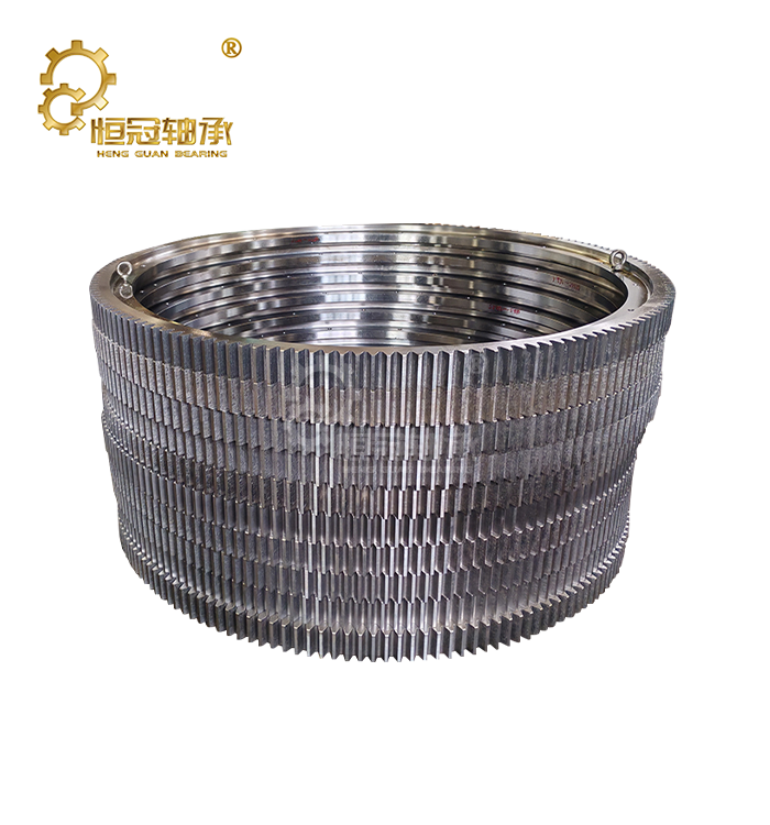
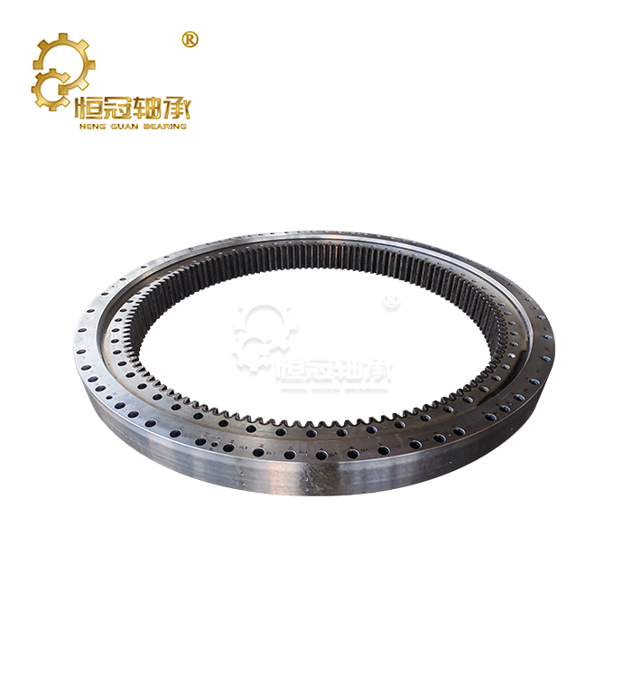
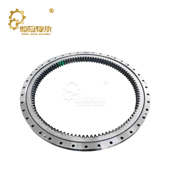
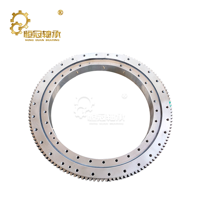
In internal gear designs, the gear teeth are on the inner ring, which makes for a small structure that is often used in places with limited installation room. The drive system is kept safe by this design, which also provides stable torque transmission.
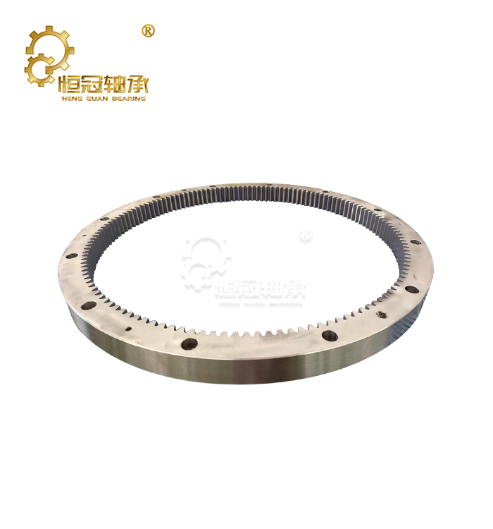
External gear setups put the teeth on the outside ring, which makes it easy to check and fix. For big industrial equipment that needs to be easy to get to and service quickly, this design is often the best choice.
When evaluating structural design, engineers usually consider:
- Load direction and distribution
- Installation space limitations
- Required rotation speed
- Maintenance accessibility
- Operating environment
A properly designed structure helps reduce uneven loading and prevents excessive stress concentration during operation.
Rolling Element Design and Contact Conditions
How forces are moved between raceways and moving parts is based on the form of the rolling elements inside a slewing gear system.
Larger rolling elements can usually carry more weight because they make a bigger contact area and lower the stress that is concentrated in one place. But making the rolling elements bigger might also make them more slippery, heavier, and harder to make.
The contact angle is another important design factor.
Different contact angles provide different load advantages:
- Larger contact angles improve axial load capacity.
- Smaller contact angles provide better balance between axial and radial loads.
- Four-point contact designs are commonly used for combined loading conditions.
For applications such as cranes and excavators, where axial and moment loads occur together, optimized contact conditions help maintain stable rotation under heavy operating forces.
Raceway Geometry and Surface Quality
Raceway design directly influences how loads are distributed throughout the bearing structure. Even small variations in geometry can increase stress concentration and accelerate fatigue damage.
Important raceway factors include:
- Raceway curvature
- Surface hardness
- Machining accuracy
- Surface roughness
- Hardened layer depth
A smooth and accurately manufactured raceway allows rolling elements to move evenly while reducing friction and wear.
For heavy-duty applications, manufacturers often use advanced machining and heat treatment processes to achieve consistent raceway performance. Proper surface quality improves fatigue resistance and helps maintain the rated load capacity of the slewing gear throughout its service life.
Material Selection and Manufacturing Quality
Steel Grade Selection
Material properties determine the strength, toughness, and fatigue resistance of a slewing gear system.
Common materials include:
- High-carbon chromium steel for standard applications
- Alloy steels for heavy shock loading conditions
- Specialized corrosion-resistant materials for marine environments
To give you an example, alloy steels like 42CrMo and 50Mn are often chosen for tough industry uses because they are both strong and resistant to pressure.
The working surroundings should guide the choice of materials. A material that works well for machines inside might not cover well enough in marine or mine settings, where rust, shaking, and contamination are common.
Heat Treatment and Surface Hardening
Heat treatment improves the mechanical properties of steel and directly affects load capacity.
Common processes include:
Quenching and Tempering
This process improves overall strength while maintaining sufficient toughness to resist impact loads.
Induction Hardening
Induction hardening creates a wear-resistant surface layer while maintaining a tougher internal structure.
A properly hardened raceway can:
- Increase contact fatigue resistance
- Reduce surface damage
- Extend operating life
- Improve load consistency
However, excessive hardness without sufficient toughness may increase the risk of cracking under shock loads. Therefore, manufacturers must balance surface hardness with core material performance.
|
|


Corrosion Resistance and Environmental Protection
Environmental exposure can significantly reduce the effective load capacity of a slewing gear.
Corrosion may cause:
- Raceway surface damage
- Reduced material strength
- Increased friction
- Accelerated fatigue failure
Applications exposed to:
- Salt water
- High humidity
- Chemical environments
- Outdoor temperature changes
Often require additional protection measures, including:
- Protective coatings
- Improved sealing systems
- Corrosion-resistant materials
- Specialized lubrication solutions
For example, port cranes and offshore equipment require stronger corrosion protection compared with indoor industrial machinery because environmental degradation directly affects long-term load performance.
Gear Tooth Design Parameters Affecting Load Performance
Tooth Profile and Load Distribution
The gear tooth design of a slewing gear determines how torque is transferred between the drive pinion and gear ring.
Involute tooth profiles are widely used because they provide:
- Smooth power transmission
- Stable contact conditions
- Better tolerance to minor alignment errors
However, improper tooth geometry can create uneven contact pressure, causing localized wear and reduced load capacity.
Modern designs may include modified tooth profiles that improve load sharing between multiple teeth and reduce stress concentration at tooth roots.
Gear Ratio and Torque Requirements
Gear ratio selection influences both operating speed and transmitted torque.
A higher gear ratio can:
- Reduce required input torque
- Improve positioning control
- Increase design complexity
A lower gear ratio can:
- Simplify manufacturing
- Reduce precision requirements
- Require higher drive torque
Engineers must balance these factors based on application requirements.
For example, precision positioning equipment may prioritize accurate movement control, while heavy construction machinery may focus more on torque capacity and durability.
Backlash Control and Positioning Accuracy
Backlash refers to the clearance between mating gear teeth. Proper backlash is necessary to accommodate:
- Thermal expansion
- Manufacturing tolerance
- Lubrication requirements
Excessive backlash may cause:
- Positioning errors
- Impact loading
- Increased vibration
Insufficient backlash may lead to:
- Tooth interference
- Increased friction
- Premature wear
For applications requiring high positioning accuracy, such as robotic systems or precision industrial equipment, controlled backlash or preloaded designs may be used.
Tooth Width and Load Sharing Capability
Tooth width affects how much force can be distributed across the gear contact area.
Wider teeth generally provide:
- Higher load distribution capacity
- Reduced contact stress
- Improved durability
However, increasing tooth width also increases:
- Component weight
- Manufacturing difficulty
- Material requirements
Therefore, gear designers must optimize tooth dimensions based on required capacity, operating conditions, and equipment limitations.
In heavy machinery applications, crown modifications and profile corrections are often applied to compensate for structural deformation and improve load sharing during operation.
Manufacturing Precision and Quality Control
Machining Accuracy
Manufacturing precision directly affects the final performance of a slewing gear.
Critical manufacturing factors include:
- Gear tooth accuracy
- Raceway dimensional tolerance
- Ring flatness
- Mounting hole accuracy
- Surface finish quality
Small dimensional errors can create uneven loading, increased vibration, and accelerated wear.
High-quality manufacturers typically perform dimensional inspections throughout production to ensure that components meet design requirements before assembly.
Inspection and Testing During Production
Reliable load performance depends on consistent quality control.
Typical inspection processes include:
- Material verification
- Hardness testing
- Gear accuracy inspection
- Raceway measurement
- Final assembly testing
For industrial buyers, reviewing quality documentation and inspection records can help verify whether a supplier can consistently produce slewing gear products that meet required load specifications.
|
|


Load Capacity Testing and Verification
Standard Testing Methods for Slewing Gear Performance
Testing is an essential step in verifying whether a slewing gear can achieve its expected load capacity under real operating conditions. Although theoretical calculations provide an initial design reference, physical testing helps confirm actual performance and identify potential weaknesses.
Common testing procedures include:
- Static load testing
- Dynamic load testing
- Fatigue life testing
- Dimensional inspection
- Performance verification
Static load testing evaluates whether the slewing gear can withstand maximum expected loads without permanent deformation. During this process, controlled forces are applied while engineers monitor structural changes, deflection, and contact conditions.
Dynamic testing focuses on operating conditions where rotation, vibration, and repeated loading occur. These tests simulate real equipment environments to evaluate long-term reliability.
Static Load Testing
Static load testing determines the maximum load capacity of a stationary or slowly moving slewing gear assembly.
The testing process typically evaluates:
- Structural deformation
- Raceway contact performance
- Gear tooth stress
- Mounting stability
This type of evaluation is particularly important for equipment that may experience occasional extreme loads, such as:
- Mobile cranes
- Heavy lifting platforms
- Large construction machinery
A successful static load test confirms that the component can resist permanent damage under specified loading conditions.
Dynamic and Fatigue Testing
Dynamic testing evaluates how a slewing gear performs during repeated operation.
Real equipment rarely operates under a single constant load. Instead, components experience:
- Continuous rotation
- Frequent acceleration
- Variable loading
- Environmental changes
Fatigue testing helps determine whether the design can maintain performance over thousands or millions of operating cycles.
Important evaluation factors include:
- Wear rate
- Lubrication performance
- Contact fatigue resistance
- Gear tooth durability
For long-life applications such as wind turbines and industrial automation systems, fatigue performance is often more important than short-term maximum load capacity.
Quality Control and Manufacturing Verification
Load capacity depends not only on design calculations but also on manufacturing consistency.
Reliable manufacturers typically implement quality control procedures covering:
- Raw material inspection
- Heat treatment verification
- Hardness testing
- Dimensional measurement
- Gear accuracy inspection
- Final assembly testing
For industrial buyers, these records provide confidence that the rated slewing gear performance is supported by actual manufacturing control.
Important quality documents may include:
- Material certificates
- Inspection reports
- Test records
- Product traceability documents
These verification processes help reduce risks caused by manufacturing variation.
Performance Monitoring and Predictive Maintenance
Real-Time Load Monitoring
Modern equipment increasingly uses monitoring technologies to evaluate operating conditions and protect slewing gear systems.
Monitoring solutions may track:
- Load changes
- Vibration levels
- Temperature variations
- Lubrication conditions
Real-time data allows operators to identify abnormal conditions before they develop into major failures.
For example, unusual vibration patterns may indicate:
- Gear tooth damage
- Raceway wear
- Lubrication problems
- Alignment issues
Predictive Maintenance Strategies
Traditional maintenance schedules are often based on fixed time intervals. However, predictive maintenance uses actual equipment data to determine when service is required.
Benefits include:
- Reduced unexpected downtime
- Improved component life
- Better maintenance planning
- Lower operating costs
For heavy equipment operators, predictive maintenance can help maintain the original load performance of a slewing gear throughout its expected service life.
Certification and Compliance Requirements
Industry Standards and Documentation
Certification helps verify that a slewing gear manufacturer follows recognized quality and performance requirements.
Common certification areas include:
- Manufacturing quality systems
- Material traceability
- Testing procedures
- Application-specific requirements
For industrial applications, buyers should evaluate whether suppliers can provide supporting documentation related to:
- Design calculations
- Load testing results
- Inspection records
- Quality management procedures
These documents help confirm that product specifications match actual manufacturing capability.
Third-Party Testing and Validation
Independent testing provides additional confidence when selecting a slewing gear supplier.
Third-party validation can verify:
- Rated load capacity
- Structural performance
- Material quality
- Manufacturing consistency
This is especially valuable for critical applications where component failure may lead to:
- Production interruption
- Safety risks
- High repair costs
Independent verification reduces uncertainty and helps buyers make more reliable purchasing decisions.
How to Select the Right Slewing Gear Based on Load Capacity
Evaluate Actual Operating Conditions
Selecting a slewing gear requires understanding the complete working environment rather than focusing only on maximum load values.
Key evaluation factors include:
- Maximum axial load
- Maximum radial load
- Maximum moment load
- Rotation speed
- Operating frequency
- Environmental exposure
A component designed for one application may not perform well in another if the loading conditions are different.
For example:
A port crane and an indoor automation system may both require rotation capability, but their load requirements, corrosion exposure, and duty cycles are completely different.
Consider Future Operating Requirements
Many equipment systems remain in service for decades. Therefore, load selection should consider future operating changes.
Engineers should evaluate:
- Potential increases in working loads
- Higher operating frequency
- More demanding environments
- Extended service expectations
Selecting a slewing gear with an appropriate capacity margin can reduce future replacement costs and improve equipment reliability.
Choose a Manufacturer with Engineering Support
Load capacity selection is not only a product decision but also an engineering decision.
A reliable manufacturer should provide:
- Application analysis
- Technical recommendations
- Customized design support
- Load calculation assistance
- Testing documentation
For complex equipment, professional engineering support helps ensure that the selected slewing gear matches actual operating conditions.
Conclusion
To choose the right slewing gear load capacity, you need to know a lot about mechanical loads, structural design, material properties, operating conditions, and the needs of the application. Performance is affected by axial loads, radial forces, and moment loads. Long-term dependability is determined by things like lubricant, climate, and manufacturing quality. If you only look at basic load rates when picking a slewing gear for heavy-duty equipment, it might not last as long or have upkeep problems that you didn't expect. A careful look at the working conditions, safety factors, test results, and provider skills can help make sure that the equipment works well for its whole time. Engineers and buying teams can choose slewing gear solutions that offer stable spinning, better longevity, and long-term value for tough industrial uses by taking into account both technical needs and operational challenges.
FAQ
1. How do I calculate the required load capacity for my specific application?
Load capacity calculations begin with a comprehensive analysis of all forces and moments acting on the bearing assembly throughout the operating envelope. Start by identifying maximum axial loads from equipment weight and operational forces, then determine peak radial loads from side forces and environmental conditions. Calculate tilting moments by multiplying loads by their distance from the bearing centerline.
2. Combine these individual load components using appropriate load combination formulas specified in relevant standards such as ISO 14728. Apply suitable safety factors based on application criticality, load variability, and maintenance practices. Consider dynamic amplification effects for applications involving acceleration, shock loading, or oscillatory motion that can increase effective loads beyond static calculations.
3. What's the difference between static and dynamic load capacity ratings?
Static load capacity represents the maximum load a bearing can support without rotation while maintaining acceptable deformation limits. This rating applies to stationary conditions or very slow rotation scenarios where rolling element fatigue is not a concern. Static ratings focus on material yield strength and contact stress limitations. Dynamic load capacity accounts for rolling contact fatigue under rotating conditions and relates to bearing service life expectations. This rating considers the cumulative effect of load cycling over millions of rotations and incorporates fatigue life calculations. Dynamic ratings are typically lower than static ratings and decrease with longer required service life.
Expert Slewing Gear Solutions from Heng Guan
Heng Guan specializes in engineering high-performance slewing gear solutions that meet the most demanding load capacity requirements across heavy industry applications. Our comprehensive design and manufacturing capabilities enable custom bearing solutions optimized for your specific operational demands and environmental conditions. As a leading slewing gear manufacturer, we provide complete technical support from initial load analysis through final installation and commissioning. Our engineering team conducts detailed load capacity assessments and recommends optimal bearing configurations that maximize performance while ensuring reliable operation throughout extended service life. Contact our technical specialists at mia@hgb-bearing.com to discuss your load capacity requirements and discover how our proven expertise can enhance your equipment reliability and operational efficiency.
References
1. Harris, T.A. and Kotzalas, M.N. "Advanced Concepts of Bearing Technology: Rolling Bearing Analysis." CRC Press, 2006.
2. Schaeffler Technologies. "Slewing Bearings: Design, Application and Maintenance Guidelines." Industrial Engineering Manual, 2019.
3. American Gear Manufacturers Association. "AGMA 6123-B06: Design Manual for Enclosed Epicyclic Gear Drives." AGMA Standards, 2006.
4. Germanischer Lloyd. "Guideline for the Certification of Wind Turbines: Chapter 7 - Drive Train and Mechanical Components." GL Wind Energy Guidelines, 2010.
5. Kania, L. "Modeling of Rollers in Calculation of Slewing Bearing with the Use of Finite Elements Method." Mechanism and Machine Theory, Volume 41, 2006.
6. International Organization for Standardization. "ISO 14728-1: Rolling Bearings - Linear Motion Rolling Bearings - Part 1: Dynamic Load Ratings and Rating Life." ISO Standards, 2017.

WHAT OUR CUSTOMERS SAY
Here is the customer's evaluation of us