

What Is a Slewing Circle in Heavy Machinery?
In heavy machinery, a slewing circle is a large-diameter rolling bearing that is intended to support rotational movement while also handling axial, radial, and moment loads. These strong parts allow machines like loaders, tower cranes, wind turbines, and mining equipment to turn 360 degrees. The slewing circle is made up of inner and outer rings that are connected by rolling elements. These elements are often combined with gear teeth to make it easier to control spinning in harsh industrial settings.

Understanding Slewing Circles: The Backbone of Rotational Heavy Machinery
Defining Slewing Circles and Their Critical Role in Industrial Equipment
Slewing circles are the basic building blocks of engineering that allow current heavy machinery to work. Specialised large-diameter bearings are the most important link between industrial equipment's fixed and rotating parts. Unlike regular bearings, which only deal with loads moving in one direction, slewing circles are designed to handle complex forces moving in multiple directions while still allowing smooth rotational movement. They are made up of precision-machined raceways, special rolling elements, and strong sealing systems. This mix makes it possible for big machinery to work well in tough conditions where other bearing options would not work. In industrial settings, these parts have to be able to keep working continuously under different loads while still being able to precisely position themselves.
How Slewing Circles Enable 360-Degree Rotation in Heavy Machinery
The unique way that slewing circles are built spreads loads over a big contact area, which is what makes them able to rotate. This mechanism for weight distribution lets heavy machinery turn easily while holding up heavy loads. The large diameter of these bearings gives them a mechanical advantage, lowering the torque needed for rotation and making operation more efficient. Modern manufacturing techniques make sure that the raceway surfaces stay in contact with the rolling elements throughout the entire rotation cycle. This stability stops binding and cuts down on wear, which makes the system last longer. Lubrication systems built into the structure of the bearings keep things running smoothly and keep them clean in tough industrial settings.
The Engineering Principles Behind Slewing Circle Design
The design of a slewing circle is based on engineering concepts that include load distribution, material choice, and geometric optimisation. The large diameter design spreads out heavy loads over a larger area, which lowers contact stress and keeps the part from breaking too soon. Material engineering uses high-quality steel alloys and certain heat treatment methods to get the best hardness and wear resistance. Geometric factors like raceway curvature, contact angle optimisation, and rolling element spacing are taken into account. These things have a direct effect on the service life, load capacity, and smoothness of spinning. Engineers use advanced computer modelling to find the best values for these parameters based on the application. This makes sure that the parameters work reliably in real-world situations.
Core Components and Technical Specifications of Slewing Circles
Inner and Outer Ring Construction: Materials and Manufacturing Standards
The effectiveness of the slewing circle is based on how the inner and outer rings are built. High-carbon steel alloys, which usually have chromium and molybdenum in them, are strong and don't wear down easily enough for commercial use. Precision casting, machining, and heat treatment are used in the manufacturing process to make sure that the raceway surfaces have a certain hardness level (55–62 HRC). To meet quality standards for manufacturing, the dimensions must be accurate to within micrometres to ensure even load distribution and smooth operation. Precision grinding is used to get the surface finish on raceways to a level that is usually between 0.2 and 0.8 micrometres Ra. These strict standards make sure that the product always works well and lasts a long time in harsh industrial settings.
Rolling Elements: Ball Bearings vs. Roller Bearings Performance Analysis
When choosing between ball and roller bearings, the performance traits are greatly affected. Because they have less friction and need less torque, ball bearings are great for uses that need to rotate at a high speed and carry moderate loads. Ball bearings can work with small misalignment because they have a point contact design. Roller bearings, on the other hand, can handle more weight because their raceways are in line contact, which makes them perfect for heavy-duty applications. Cross roller designs are very rigid and precise, which is especially useful in situations where precise placement is needed. Choosing between configurations relies on the application's load needs, rotational speed, and level of accuracy.
Sealing Systems and Lubrication Requirements for Optimal Performance
Internal parts are kept clean, and fluids that are needed for smooth operation are kept in by sealing systems that work well. Rubber lip seals, labyrinth seals, and metal shields are all used in multi-stage sealing designs to provide full safety. Temperature changes, pressure differences, and exposure to industrial contaminants are all things that these systems have to deal with. Lubrication needs depend on the working conditions and the needs of the application. Grease lubrication is easy to use and protects well in most situations, while oil lubrication systems cool better and remove contaminants continuously. Scheduling lubrication intervals correctly keeps things running at their best throughout their service life and stops them from wearing out too quickly.
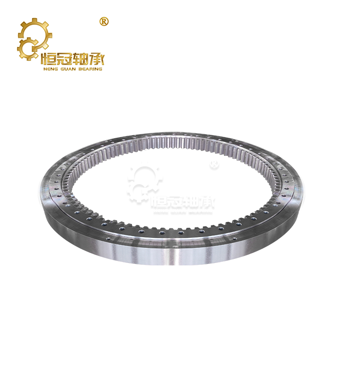
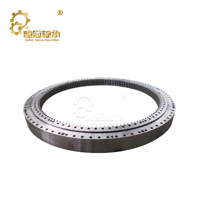
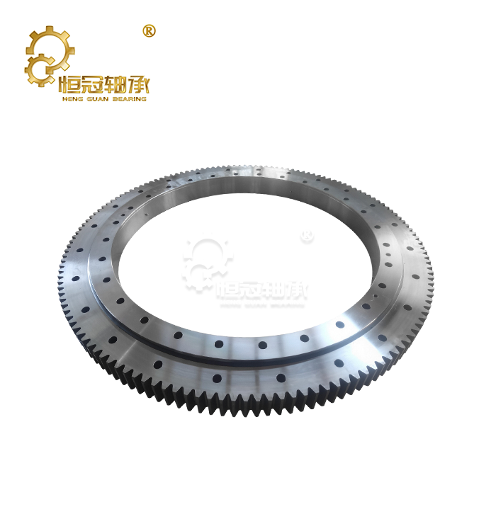
Gear Integration: Internal vs. External Gear Configurations
Depending on the needs of the application and the available room, the different ways to integrate gear offer different benefits. Internal gear configurations allow for small designs with protected gear teeth, which lowers the risk of contamination and the amount of upkeep that needs to be done. The internal arrangement also offers higher gear ratios within smaller envelope dimensions. External gear designs make it easier to replace and do maintenance. In heavy-duty applications, these configurations often allow for bigger gear modules and higher torque gearbox capacities. When choosing between internal and external gears, room constraints, ease of maintenance, and torque needs must all be taken into account.
Load Capacity Specifications: Axial, Radial, and Moment Load Ratings
Specifications for load capacity set the safe and reliable limits for function. Axial load rates show the most thrust force that the bearing can handle, which is important for uses that have a lot of vertical loads. Radial load ratings show the highest forces that can be applied perpendicular to the rotation axis. These ratings are important for applications that load from the side. Moment load ratings show how well the bearing can handle tilting forces, which are important for applications that have offset loads or toppling moments. These requirements are set by strict tests and calculations that take into account the properties of the material, its shape, and safety concerns. Knowing these scores helps you choose the right application and keeps things from breaking down too soon.
Types of Slewing Circles and Their Industrial Applications
Single-Row Ball Bearing Slewing Circles for Light-Duty Applications
Single-row ball bearing designs provide cost-effective solutions for slewing circles for light to moderate load applications. These configurations feature four-point contact geometry that handles combined loads efficiently while maintaining compact dimensions. The simplified design reduces manufacturing complexity and overall costs, making it attractive for budget-conscious applications. Applications for single-row designs include small mobile cranes, aerial work platforms, and packaging machinery, where loads remain within moderate ranges. The reduced complexity also means easier maintenance and replacement procedures, contributing to lower total ownership costs. However, load capacity limitations restrict their use in heavy-duty industrial applications.
Double-Row Ball Bearing Systems for Enhanced Load Distribution
Double-row ball bearing configurations provide increased load capacity through enhanced load distribution across two rows of rolling elements. This design improves rigidity and reduces deflection under load, making it suitable for medium-duty applications requiring higher precision. The dual-row arrangement also provides redundancy, improving reliability in critical applications. These systems find application in medium-sized construction equipment, industrial turntables, and automation systems where moderate to high loads combine with precision requirements. The improved load distribution extends service life compared to single-row designs while maintaining reasonable cost levels.
Cross Roller Bearings for High-Precision Heavy Machinery
Cross roller bearing designs represent the premium solution for applications demanding exceptional precision and rigidity. The alternating arrangement of cylindrical rollers provides uniform load distribution and minimises elastic deformation. This configuration achieves the highest precision levels available in slewing circle technology. Applications requiring cross roller designs include precision positioning systems, medical equipment, aerospace applications, and high-accuracy machine tools. While these systems command premium pricing, their superior performance justifies the investment in critical applications where precision directly impacts operational success.
Three-Row Roller Slewing Circles for Maximum Load Capacity
Three-row roller configurations deliver maximum load capacity for the most demanding heavy-duty applications. The design incorporates separate rows optimised for axial and radial loads, providing exceptional capacity in all load directions. This arrangement handles the extreme forces encountered in large mining equipment, port machinery, and heavy lifting applications. The complexity of three-row designs requires precise manufacturing and assembly procedures to ensure proper load sharing between rows. While these systems represent the highest cost option, their unmatched load capacity makes them essential for applications where no alternative exists.
Application-Specific Examples: Excavators, Cranes, and Wind Turbines
Excavator applications demand slewing circles capable of handling dynamic loads while providing smooth rotation for operational efficiency. The bearing must support the machine weight, boom loads, and dynamic forces from digging operations. Typical designs utilise single or double-row configurations depending on machine size and capacity requirements. Tower crane applications require exceptional moment load capacity to handle overturning forces from lifted loads. Three-row roller designs commonly serve these applications, providing the necessary capacity and rigidity. Wind turbine applications present unique challenges with continuous rotation requirements and exposure to environmental conditions, necessitating specialised sealing and lubrication systems.

Installation Process and Maintenance Best Practices
Pre-Installation Requirements: Foundation Preparation and Alignment
Proper foundation preparation ensures successful slewing circle installation and long-term performance. The mounting surface must achieve flatness tolerances within specified limits, typically requiring machining or precision grinding. Surface finish requirements ensure uniform load distribution and prevent stress concentrations that could lead to premature failure. Alignment verification using precision measurement tools confirms that mating surfaces maintain proper geometric relationships. Temperature considerations during installation account for thermal expansion effects that could affect final alignment. Environmental protection during installation prevents contamination that could compromise performance.
Step-by-Step Installation Guidelines for Industrial Applications
Installation procedures begin with a thorough inspection of all slewing circle components to verify condition and compliance with specifications. Proper handling techniques prevent damage to precision surfaces and sealing elements. Sequential bolt tightening procedures ensure uniform loading and prevent distortion of the bearing rings. Torque specifications must be followed precisely to achieve proper preload and prevent loosening during operation. Installation documentation records critical parameters and provides a reference for future maintenance activities. Final verification procedures confirm proper installation before commissioning the equipment.
Torque Specifications and Bolt Pattern Considerations
Bolt torque specifications are calculated based on bolt grade, thread pitch, and desired clamping force. Progressive tightening sequences ensure uniform load distribution around the bolt circle. Proper torque values prevent both under-tightening, which leads to loosening and over-tightening, which can damage components. Bolt pattern design considerations include bolt size, spacing, and material selection appropriate for the application loads. Regular torque verification during initial operation confirms that proper clamping forces are maintained. Documentation of torque values provides a baseline reference for maintenance activities.
Preventive Maintenance Schedules for Extended Service Life
Operating conditions, load factors, and manufacturer suggestions are used to make preventive maintenance schedules. Regular lubrication times make sure that the system is protected and works well. Visual checks find damage or wear that is happening before it gets too bad to fix. Tracking rotational torque, shaking levels, and temperature are all parts of operational monitoring that help find problems before they get too bad. Checking the strength of the bolts, inspecting the seals, and servicing the lubrication system are all routine maintenance tasks. Keeping records of maintenance tasks gives us a history of operations for analysing reliability.
Troubleshooting Common Issues: Wear Patterns and Performance Degradation
Common patterns of wear show specific operating issues that need to be fixed. Uneven wear patterns are a sign of a mismatch or bad loading conditions. Too much wear means there are problems with contamination or not enough grease that need to be fixed right away. Signs of performance decline include higher rotational resistance, strange noises, or vibrations while the machine is running. Systematic fixing steps find the root causes and the right steps to take to fix them. Taking action early on stops small problems from getting worse and needing full bearing replacement.
Selecting the Right Slewing Circle for Your Heavy Machinery
Load Calculation Methods: Determining Your Equipment Requirements
Accurate load calculation forms the foundation of proper slewing circle selection. Static load analysis considers maximum weights and forces under normal operating conditions. Dynamic load factors account for acceleration, deceleration, and shock loads encountered during operation. Safety factors provide a margin for unexpected loads and ensure reliable performance. Load calculation methodologies incorporate industry standards and proven engineering practices. Computer modelling tools help analyse complex loading conditions and optimise bearing selection. Professional engineering consultation ensures accurate analysis for critical applications where failure consequences are severe.
Environmental Factors: Temperature, Contamination, and Weather Resistance
Environmental conditions significantly influence bearing selection, slewing circle and performance expectations. Temperature extremes affect lubrication properties and material expansion rates. Contamination exposure from dust, water, or chemicals requires appropriate sealing and material selection. Weather resistance considerations include UV exposure, precipitation, and temperature cycling effects. Special material treatments and coating options provide enhanced environmental resistance for extreme conditions. Sealing system selection balances protection requirements with operational accessibility. Environmental factor analysis ensures that selected bearings provide reliable performance throughout their intended service life.
|
|


Conclusion
Slewing circles represent critical components that enable the functionality of modern heavy machinery across diverse industrial applications. Understanding their design principles, component specifications, and application requirements ensures optimal selection and performance. Proper installation, maintenance, and supplier selection directly impact operational reliability and total ownership costs. The investment in quality slewing circles pays dividends through extended service life, reduced downtime, and improved equipment performance in demanding industrial environments.
FAQ
1. What is the typical service life of a slewing circle in heavy machinery?
Service life varies significantly based on application conditions, load factors, and maintenance practices. Quality slewing circles operating under normal conditions with proper maintenance typically achieve 10,000 to 30,000 operational hours. Heavy-duty applications with extreme loads may require replacement every 5,000 to 15,000 hours, while light-duty applications can exceed 50,000 hours when properly maintained.
2. How do I determine if my slewing circle needs replacement?
Key replacement indicators include increased rotational resistance during operation, unusual noise or vibration during rotation, visible wear on gear teeth or raceways, excessive play or backlash in the system, and oil leakage from sealing systems. Regular monitoring of these parameters helps identify developing problems before catastrophic failure occurs.
3. Can slewing circles be customised for specific heavy machinery applications?
Reputable manufacturers offer extensive customisation capabilities, including specific bore dimensions, mounting configurations, gear ratios, sealing solutions, and special materials for extreme environments. Custom engineering solutions typically require detailed application analysis and may involve longer delivery schedules compared to standard products.
4. What distinguishes slewing circles from standard turntable bearings?
While these terms are sometimes used interchangeably, slewing circles typically refer to larger, heavy-duty bearings designed specifically for industrial machinery applications. Turntable bearings may include smaller precision units for lighter applications. Both enable rotational movement but differ significantly in load capacity, size ranges, and application scope.
Partner with Heng Guan for Superior Slewing Circle Solutions
Heng Guan bearing technology delivers precision-engineered slewing circle solutions designed to meet the most demanding industrial applications. Our comprehensive product range spans 20-10000mm diameter bearings with accuracy grades from P0 to P4, ensuring optimal performance for your specific requirements. Located in Luoyang, China's renowned bearing manufacturing centre, we combine advanced production capabilities with rigorous quality control processes.
Our experienced engineering team specialises in customised designs for construction, mining, lifting, and metallurgical applications. Whether you require single-row configurations for light-duty applications or three-row roller systems for maximum load capacity, we provide solutions backed by comprehensive technical support. As a trusted slewing circle manufacturer, we maintain global quality standards while delivering cost-effective solutions that enhance equipment reliability and operational efficiency. Contact mia@hgb-bearing.com to discuss your specific requirements and discover how our proven expertise can optimise your heavy machinery performance.
References
1. Harris, T.A., and Kotzalas, M.N. "Advanced Concepts of Bearing Technology: Rolling Bearing Analysis, Fifth Edition." CRC Press, 2007.
2. Warda, B., and Chudzik, A. "Effect of Ring Misalignment on the Fatigue Life of the Slewing Bearing." Materials Science and Engineering, 2016.
3. Kania, L. "Modelling of Rollers in Calculation of Slewing Bearing with the Use of Finite Elements." Mechanism and Machine Theory, 2013.
4. ISO 12044-1:2014. "Rolling bearings - Single row angular contact ball bearings - Chamfer dimensions for outer ring non-thrust side." International Organisation for Standardisation, 2014.
5. Daidié, A., Chaib, Z., and Ghosn, A. "3D Simplified Finite Elements Analysis of Load and Contact Angle in a Slewing Ball Bearing." Journal of Mechanical Design, 2008.
6. Aguirrebeitia, J., Abasolo, M., Aviles, R. y Fernández de Bustos, I. "General Static Load-Carrying Capacity for the Design and Selection of Four Contact Point Slewing Bearings: Finite Element Calculations and Theoretical Model Validation." Finite Elements in Analysis and Design, 2012.

WHAT OUR CUSTOMERS SAY
Here is the customer's evaluation of us