




Pinion Gear Shaft vs. Solid Gear Shaft: Key Differences
Every hour that a gearbox sits not in use, it costs your company money. In many drivetrains, the weak spot is not the gear or the Shaft, but the junction between the two. Some common disappointments are: keyways and press fittings that loosen and fret after months of cyclic pressure; completed parts that just never seem to line up, creating vibration and early bearing wear; and the challenge of finding a supplier that can manufacture precisely to your designs. In every powertrain, the choice between a pinion gear shaft and a solid gear shaft will affect efficiency, service life, and maintenance cost. The gear teeth and the shaft for a pinion gear shaft are machined from a single forged blank, while generally a solid gear shaft joins a plain shaft with a separate gear. Heng Guan Bearing's tutorial analyzes the two designs so that you can decide which one is best for your application.
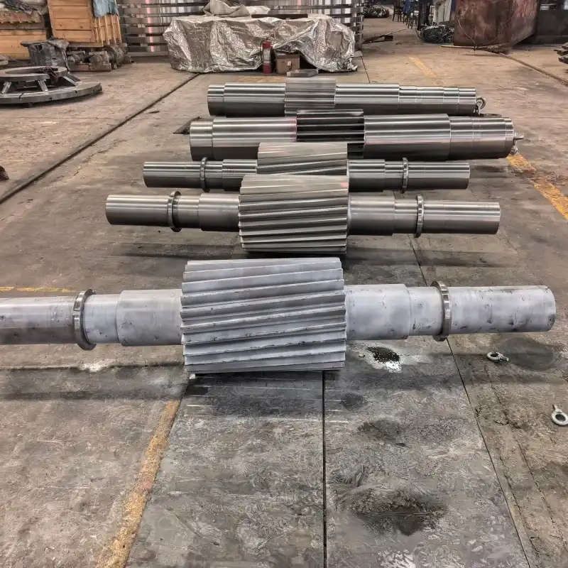
What Is the Structural Difference Between a Pinion Gear Shaft and a Solid Gear Shaft?
The pinion gear shaft is a single piece. The tiny gear and shaft are produced from a single forged blank; thus, there is a continuous load path with no connection in between. A gear wheel is usually placed onto a plain shaft by keys, splines, or a press fit to provide a solid gear shaft. The pinion shaft range offered by Heng Guan Bearing has diameters ranging from φ100 mm to φ1000 mm and lengths ranging from 100 mm to 3000 mm. Gear modules range from M3 to M20 and may be modified. The pinion gear and shaft are a single body, which results in a compact design and inherent concentricity from the very first machining process. If you have limited room, this is a good reason to have a good look at an integrated design.
| Configuration | Primary Characteristic | Typical Application |
|---|---|---|
| Pinion gear shaft (integrated) | Gear and shaft in one forged body; compact, accurate transmission ratio | Reducers, gearboxes and heavy-duty drives where space and precision matter |
| Solid gear shaft (assembled) | Separate gear fitted to a plain shaft; gear can be replaced on its own | General transmissions and flexible assemblies |
How Do Torque Transmission and Load Capacity Compare Between the Two Shaft Designs?
The pinion shaft has no crossing of a keyway or interference joint to transmit torque. The power transmits smoothly from the primary mover to the driving equipment. The continuous route eliminates micro-slip and lowers stress concentration, and Heng Guan Bearing’s technical data shows efficiency improvements of up to 15% over press-fit assemblies. A solid gear shaft is nevertheless a versatile option when the gear itself may require changing. The pinion gear shaft is the best choice when the loads are large, and the position has to be exact. The pinion gear and the shaft bear bending and torsion together as one. The bearing seats are CNC-ground, and they preserve concentricity within 0.01 mm. This reduces vibration and extends the lifespan of the bearings around the shaft. Let's see the differences side by side.
| Feature | Pinion Gear Shaft | Solid Gear Shaft |
|---|---|---|
| Construction | Single forged blank | Gear mounted on shaft |
| Load path | Continuous | Passes through joint |
| Alignment | Fixed by machining | Depends on assembly |
| Torque transfer | No keyway or press-fit joint in the gear section | Relies on key, spline, or press fit |
| Typical use | Heavy-duty drives | General transmissions |
Material Selection, Gear Integration, and Manufacturing Processes
The material determines the strength limit of any shaft. Heng Guan Bearing produces each pinion shaft using alloy steels, such as 42CrMo, 20CrMnTi, and 40Cr, which are suitable for forging and heat treatment. The pinion gear shaft is rough-turned from a forged blank, and the teeth are cut using CNC and gear hobbing equipment. The product is then heat-treated and finish-ground for the requisite precision. The surface of the tooth is hardened by carburizing while the core remains robust, giving a high contact fatigue resistance in high-cycle usage. The gear shaft is a solid shaft; the gear and shaft are built separately and then combined, and the route is divided. The integrated method eliminates the assembly step and allows engineers more control over tooth-to-journal alignment. Unit weights range from 5kg to 500kg. Customization is available based on your designs, samples, or OEM standards. Below you will see the table with the main technical specifications of our pinion shaft.
Technical Specifications
| Parameter | Specification |
|---|---|
| Shaft Diameter | φ100mm - φ1000mm |
| Total Length | 100mm - 3000mm |
| Gear Module | M3 - M20 (customizable) |
| Unit Weight | 5kg - 500kg |
| Base Material | 42CrMo, 20CrMnTi, 40Cr alloy steel |
| Core Hardness | HRC 28-32 (after heat treatment) |
| Tooth Surface Hardness | HRC 58-62 (after carburizing) |
| Gear Accuracy Grade | GB 5-6 (ISO equivalent) |
| Connection Types | Keyway, spline, flange |
| Tooth Profile Options | Spur, helical, bevel |
Not sure which pinion gear shaft configuration your drive needs? Send your requirements to mia@hgb-bearing.com, and our engineers will recommend the best pinion gear and shaft configuration.
Which Shaft Design Offers Better Durability and Fatigue Resistance in Industrial Applications?
Durability begins with a component’s capacity to survive millions of load cycles. The shaft body is able to endure torsional and bending fatigue more consistently because there is no key, spline, or press-fit contact on the pinion gear and shaft where fretting and stress risers often start. Shoulders are filleted to specified radii to reduce stress concentrations. Forged grain flow, following the contour of the part, further enhances toughness in mining, port machinery, metallurgy, and crushing equipment. Prior to shipping, each shaft undergoes ultrasonic fault identification, analysis of chemical composition, hardness testing, tooth profile measuring, and dimensional verification. Customers switching to our shafts have noted consistent dependability and extended service life. A good pinion shaft will decrease vibration, which will preserve the bearings surrounding it. The table below illustrates why the integrated design is the choice of many purchasers.
| Efficiency Factor | Assembled Gear + Shaft | Integrated Pinion Gear Shaft |
|---|---|---|
| Interface micro-slip | Present | Eliminated |
| Stress concentration | Higher | Lower |
| Misalignment bearing load | Possible | Minimized |
Even a well-built shaft performs best with simple, structured care:
| Stage | Action Required |
|---|---|
| At installation | Check shaft runout at the bearing seats with a dial indicator; it should not exceed 0.02 mm. |
| First operating hours | Run the gear at reduced load and monitor temperature and vibration levels. |
| Routine maintenance | Lubricate according to your equipment manufacturer's oil type and change intervals, and listen for unusual noise or vibration. |
| High-duty applications | Measure tooth thickness periodically and replace the part before wear exceeds 15% of the original dimension. |
| Storage | Apply a corrosion-preventive coating and store in a climate-controlled area. |
Conclusion
The solid gear shaft is perfect for flexible assemblies, and the pinion gear shaft is a small, continuous, and efficient option for demanding demands. Match design to load, space, and service objectives for dependable performance and fewer unexpected pauses. Heng Guan Bearing is with you all the way from design to final inspection. Contact Luoyang Heng Guan for your custom pinion gear shaft solution now.
FAQ
Q: What is a pinion gear shaft?
A: It is a single component that combines a small gear and a shaft, made from one forged blank so that torque passes through a continuous body with no gear-to-shaft joint.
Q: Which materials are used?
A: 42CrMo, 20CrMnTi and 40Cr alloy steels, heat-treated to a core hardness of HRC 28-32, with carburized tooth surfaces reaching HRC 58-62.
Q: What sizes are available?
A: Diameters of φ100–φ1000 mm and lengths of 100–3000 mm, with gear modules from M3 to M20.
Q: Can it be customized?
A: Yes, based on drawings, samples, or OEM specifications. Standard arrangements typically ship within 3-4 weeks and custom designs within 6-8 weeks, and single-piece orders are accepted.
Q: Why choose an integrated design?
A: It removes the gear-to-shaft joint, which lowers stress concentration and micro-slip and improves efficiency by up to 15% compared with press-fit assemblies.
How Luoyang Heng Guan Solves Your Pinion Gear Shaft Challenges
At Luoyang Heng Guan Bearing Technology Co., Ltd., as a pinion gear shaft supplier with more than 20 years of experience in bearing and precision machining, we combine engineering expertise, manufacturing capability, and technical support to deliver shafts that minimize downtime and maximize reliability:
- Shaft diameters from φ100 mm to φ1000 mm, lengths up to 3000 mm, modules M3 to M20
- ISO 9001 certified production with ultrasonic flaw detection and full dimensional inspection
- Custom manufacturing from drawings, samples, or OEM specifications, from single pieces to volume orders
- Proven solutions for mining, port machinery, metallurgy, crushing and power transmission equipment
Facing drivetrain failures or fitment issues? Contact Us at mia@hgb-bearing.com today with your drawings and requirements to receive professional engineering support and a tailored quotation.
References
1. Budynas, R. G., & Nisbett, J. K. Shigley's Mechanical Engineering Design. McGraw-Hill Education.
2. Norton, R. L. Machine Design: An Integrated Approach. Pearson.
3. Radzevich, S. P. Dudley's Handbook of Practical Gear Design and Manufacture. CRC Press.
4. Oberg, E., et al. Machinery's Handbook. Industrial Press.
5. ISO 6336: Calculation of Load Capacity of Spur and Helical Gears. International Organization for Standardization.
6. ANSI/AGMA 2001-D04: Fundamental Rating Factors and Calculation Methods for Involute Spur and Helical Gear Teeth. American Gear Manufacturers Association.

WHAT OUR CUSTOMERS SAY
Here is the customer's evaluation of us