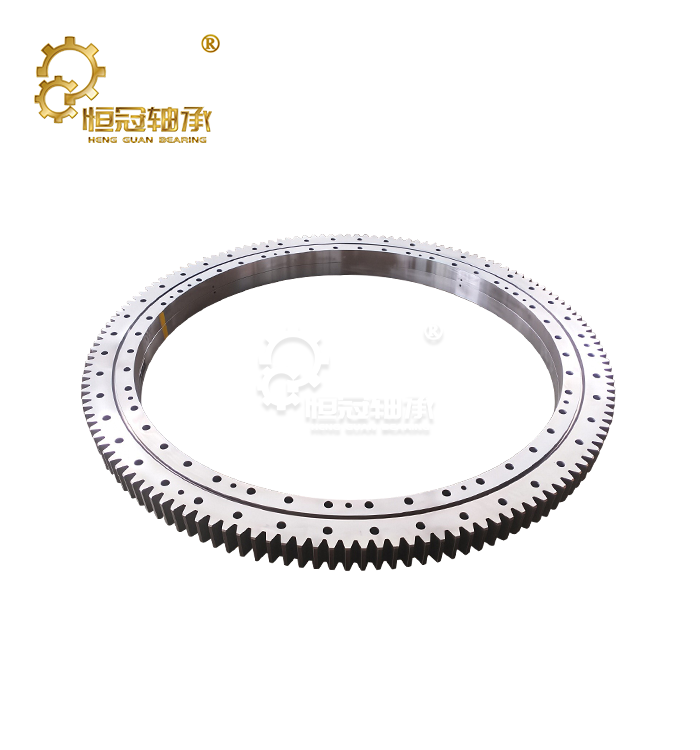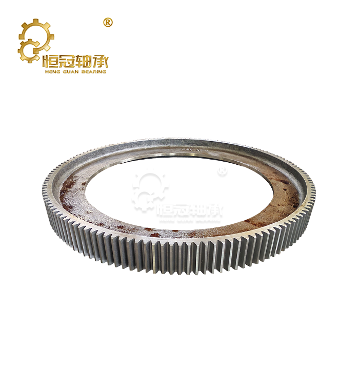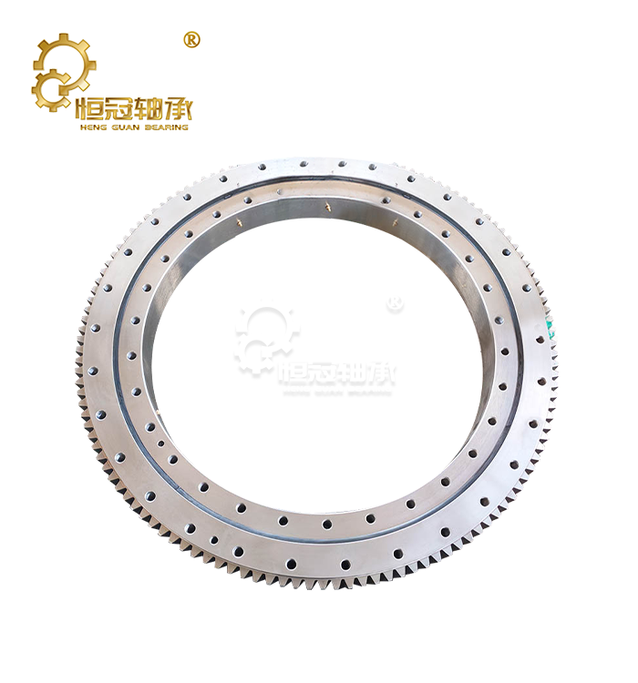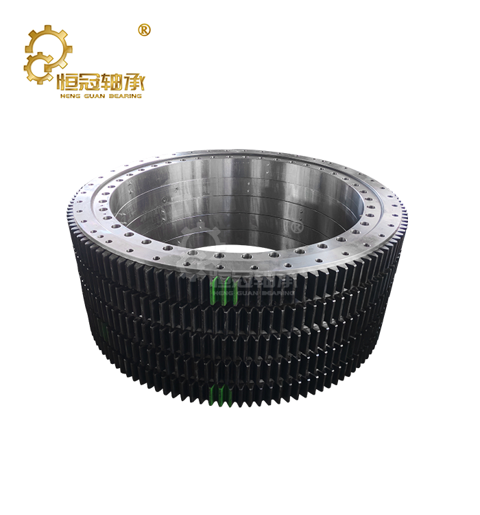




Can Slewing Circles Handle Combined Loads?
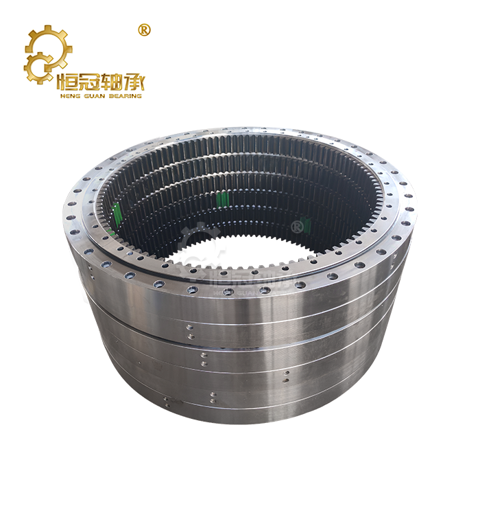
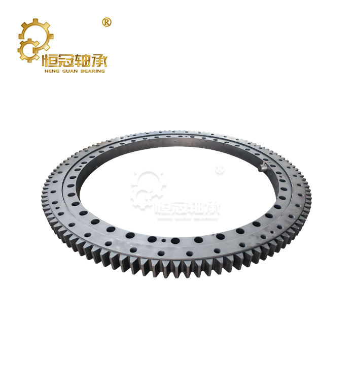
Slewing circles are indeed designed to handle mixed loads well. Modern slewing circle designs use complex bearing arrangements that handle radial, axial, and moment forces at the same time. Heavy machinery today often has to work in tough conditions with many forces acting on rotating parts at the same time. In these situations, a spinning part has to be able to handle not only vertical or horizontal forces, but also toppling moments caused by uneven loads, acceleration, and outside environmental factors. It is built so that slewing rings can work in these tough conditions. They can handle mixed axial, radial, and moment loads while keeping smooth spinning and structural stability. This is possible with carefully controlled manufacturing methods, high-strength materials, and a raceway design that has been optimised. Choosing the right slewing option for machines like loaders, cranes, wind turbines, and industrial moving platforms is important for making them more reliable, lowering the amount of upkeep they need, and making them last longer.

Understanding Combined Loads in Slewing Circle Applications
What Are Combined Loads and Why Do They Matter?
When several forces act on a rotating bearing system at the same time, this is called a combined load. Combined loading is different from simple loading, where one force direction is dominant. It involves the combination of different forces that form more complicated internal stress patterns.
These are the three main types of loads:
Side Loads
Axial loads work in a straight line along the bearing axis. Most of the time, they are made by:
- How much equipment weighs, how to lift things, hydraulic forces, and vertical structure loads.
- As an example, the weight of the moving frame and the load being moved put horizontal pressure on a crane slewing system.
Radial Loads
Radial loads act perpendicular to the bearing axis. These forces often come from:
- external operating resistance;
- machine movement;
- uneven ground conditions;
- side forces during operation.
In excavators, radial forces can change continuously as the machine digs, swings, and moves materials.
Moment Loads
Moment loads are created when forces act at a distance from the bearing center. These forces generate overturning effects that can significantly increase stress on the rotating system.
Typical sources include:
- extended crane booms;
- excavator attachments;
- wind pressure on large structures;
- uneven material distribution.
Because moment loads create additional stress through leverage, they are often one of the most important factors during bearing selection.
Why Combined Loading Is More Challenging Than Single-Direction Forces
When a bearing is made for a single direction of force, the stress distribution is pretty easy to guess. When different forces are added together, however, they interact in ways that change how stress moves through the bearing system. For instance, raising the rotational force can change how the rolling elements and raceways touch each other. When radial and moment loads are added, there may be higher stress concentrations in some contact areas.
These changing factors make a number of engineering problems:
- Uneven load distribution; higher contact pressure, faster wear and tear; and greater sensitivity to mistakes in installation.
- Because of this, engineers often use complex math tools like finite element analysis (FEA) and dynamic load modelling to check how well a bearing works in real-world situations.
A good design doesn't just make the bearings bigger. Instead, it finds the best internal shape, materials, and load paths to make the performance fair.
How Slewing Circles Manage Multi-Directional Forces
Raceway Geometry and Load Distribution Design
Raceway design is one of the most important things that affects how well a joint load works. How forces are sent between the rolling elements and the bearing rings is controlled by the raceway. A well-designed raceway spreads loads out more evenly and lowers stress in one area. A lot of people use four-point contact systems because they let each moving part handle pressure from different directions.
Some of the benefits of this style are:
- Better handling of axial loads, higher moment strength, even spread of rotational forces, and small fitting requirements.
- Manufacturers can change things about the bearing design, like the contact angle, the curvature of the raceway, and the arrangement of the rolling elements, to meet the needs of different applications.
Large Diameter Structure Improves Moment Resistance
When dealing with overturning moments, the large diameter of slewing systems naturally helps. Moment resistance depends a lot on how far apart the load points are. A bigger girth makes the load arm longer, which makes the system better at resisting forces that try to turn it.
Because of this, large-diameter spinning parts are often used in:
- industrial platforms, cranes, loaders, and wind turbines.
- It's not always true that a bigger bearing diameter means better performance. The general plan also needs to take into account:
- Strength of the material; accuracy of the track, mounting frame, and working conditions.
- A well-designed system strikes a good balance between size, strength, and how easy it is to install.
Material Strength and Heat Treatment Performance
For industrial buyers, selecting the right slewing ring bearings supplier is as important as selecting the correct bearing type. A reliable manufacturer should provide technical support throughout the purchasing process.
People often choose high-quality bearing steels like 42CrMo and 50Mn because they offer:
- High mechanical strength, good toughness, and resistance to wear and tear.
- By finding the right mix between surface hardness and internal stiffness, heat treatment improves performance even more.
- As an example, induction hardening can make the core structure stronger while also making the raceways less likely to wear down. This helps the bearing handle being loaded and unloaded many times without deforming too much or breaking down too soon.
Protective coats and surface treatments may also be used on equipment that works in tough conditions, such as:
maritime places, sites in the ocean, and chemical production plants.
Engineering Features That Improve Combined Load Performance
Optimized Contact Angle and Rolling Element Arrangement
How forces are passed between the moving parts and raceways is based on the contact angle.
When the contact position is right, it helps spread loads more evenly between:
- There are moment forces, axial forces, and rotary forces.
- Engineers have to balance different performance needs instead of just optimising one load direction for applications where the load conditions change.
- Another important thing to think about is the rolling element spacing. Even division keeps different parts from having to carry too much weight, which stops uneven wear and makes the system more stable.
Structural Rigidity and Deformation Control
When big loads are put on a piece of equipment at once, bearing damage can affect:
- efficiency of movement; activation of gears; placement of tools.
- A rigid bearing structure helps keep performance stable by limiting the amount of deformation that happens during use.
This is quite important for:
- industrial equipment that needs to be precise, controlled machinery, and lifting systems that need to be placed correctly.
- Before finalising a design, manufacturers usually use engineering analysis to check how rigid the structure is.
Load Capacity Evaluation for Combined Loading Conditions
Understanding Static and Dynamic Load Ratings
Static and dynamic load ratings provide different information about bearing performance.
Static Load Rating
Static capacity describes how much load a bearing can support when stationary or operating at very low speed without permanent deformation.
For combined loading applications, static evaluation must consider the interaction between:
- axial forces;
- radial forces;
- moment loads.
A bearing may meet individual load requirements but still require additional evaluation when multiple forces act together.
Dynamic Load Rating
Dynamic capacity considers bearing performance during rotation.
Since equipment loads often change during operation, engineers need to evaluate:
- operating cycles;
- load variations;
- acceleration and deceleration;
- environmental influences.
For mobile machinery, dynamic analysis is especially important because loading conditions can change continuously.

Load Capacity Evaluation for Combined Loading Conditions
Moment Load Calculation and Safety Factor Selection
Moment loads are often the most critical consideration when selecting Slewing circles for heavy-duty applications. Unlike simple axial or radial forces, moment loads create rotational stress around the bearing center, increasing pressure on specific contact areas.
Accurate moment load evaluation requires engineers to consider:
- equipment weight distribution;
- working radius;
- external forces;
- acceleration and braking effects;
- unexpected shock loads.
Safety factors are also essential because real operating conditions rarely remain constant. Heavy equipment may experience sudden impacts, uneven loads, or environmental changes that exceed normal design assumptions. For safety-critical applications such as cranes and lifting equipment, conservative safety margins help prevent premature fatigue and improve operational reliability.
Load Interaction Between Axial and Radial Forces
Axial and radial forces rarely act independently in real applications. Their interaction affects the internal contact conditions of the bearing and influences overall load capacity.
For example, a rotating excavator may experience:
- vertical loads from the upper structure;
- side forces during digging;
- moment loads from the extended boom.
When these forces combine, the bearing must distribute stress across multiple contact areas while maintaining smooth rotation. Advanced engineering calculations help determine whether a selected configuration can safely handle the expected load combination. This evaluation is especially important when equipment operates frequently under changing conditions.
Fatigue Life Prediction Under Variable Operating Conditions
Traditional bearing life calculations often assume stable loading conditions. However, heavy machinery usually experiences constantly changing forces.
Variable combined loading requires consideration of:
- load frequency;
- operating cycles;
- peak stress events;
- environmental factors.
By analyzing actual load patterns, engineers can estimate service life more accurately and select a bearing design that matches the real application.
Proper life prediction helps avoid:
- unexpected downtime;
- excessive maintenance;
- premature component replacement.
Industrial Applications of Slewing Circles Under Combined Loads
Excavator Operations: Handling Swing, Digging, and Lifting Forces
Excavators are one of the most common examples of equipment exposed to combined loading conditions.
During operation, the slewing system must simultaneously handle:
- upper structure weight;
- hydraulic digging forces;
- swing acceleration;
- uneven material loads.
The load pattern changes continuously as the excavator moves between digging, lifting, and rotating operations.
To withstand these conditions, excavator slewing solutions typically require:
- strong raceway structures;
- reliable sealing systems;
- contamination protection;
- optimized internal load distribution.
A properly selected bearing helps maintain smooth rotation while reducing wear caused by repeated shock loading.
|
|


Crane Systems: Managing High Moment Loads During Lifting
Crane applications create some of the highest combined load demands because the load position changes constantly with boom movement.
A crane slewing system must support:
- the weight of the rotating structure;
- suspended loads;
- wind forces;
- dynamic movement during operation.
Moment loads become especially significant when lifting heavy loads at extended working distances.
For these applications, engineers often select designs with:
- higher moment capacity;
- increased structural rigidity;
- enhanced fatigue resistance.
Reliable load management is essential because bearing performance directly affects equipment safety and operational efficiency.
Wind Turbine Systems: Balancing Environmental and Operational Forces
Wind turbines present unique combined load challenges because they operate continuously under changing environmental conditions.
The slewing components used in yaw and positioning systems must withstand:
- wind pressure;
- rotor imbalance;
- gravitational forces;
- continuous rotation cycles.
Unlike indoor machinery, wind energy equipment is exposed to temperature changes, moisture, and corrosive environments.
To achieve long-term reliability, manufacturers often use:
- corrosion-resistant coatings;
- optimized lubrication systems;
- fatigue-resistant materials.
These improvements allow wind turbine systems to maintain stable operation in demanding outdoor conditions.
Solar Tracking Systems: Maintaining Precision Under Wind Loads
Solar tracking equipment requires both accurate positioning and sufficient load capacity. Although solar systems generally experience lower mechanical loads than cranes or excavators, they must maintain precise movement over long operating periods with slewing ring bearings.
The slewing system needs to handle:
- wind pressure;
- thermal expansion;
- Repeated positioning cycles.
Design considerations include:
- low rotational resistance;
- accurate mounting interfaces;
- reliable outdoor protection.
These features help maintain tracking accuracy while extending equipment service life.
Selecting the Right Slewing Circle for Combined Load Applications
Evaluate Actual Operating Conditions Before Selection
Choosing a slewing solution should begin with a complete understanding of the equipment operating environment.
Engineers should evaluate:
- maximum and average loads;
- rotation speed;
- duty cycle;
- temperature range;
- contamination exposure.
Selecting only based on basic load capacity may result in insufficient performance because combined forces often create higher internal stress than individual loads suggest.
Choose the Correct Bearing Configuration
Different applications require different structural designs.
Common options include:
Single-Row Four-Point Contact Designs
Suitable for applications requiring:
- compact dimensions;
- moderate combined loads;
- smooth rotation.
Typical uses include:
- light construction equipment;
- industrial positioning systems;
- solar tracking devices.
Double-Row or Roller Configurations
Better suited for:
- higher load requirements;
- heavy machinery;
- applications with greater rigidity demands.
These designs provide increased contact area and improved load distribution when operating under severe conditions.
Consider Sealing and Lubrication Requirements
Combined loading creates additional challenges for lubrication because changing forces affect contact pressure and friction conditions.
A suitable maintenance strategy should consider:
- lubricant type;
- operating temperature;
- contamination risk;
- relubrication frequency.
Effective sealing prevents:
- dust contamination;
- moisture entry;
- lubricant loss.
This is especially important for outdoor machinery operating in mining, construction, and marine environments.
Installation and Maintenance Practices for Long-Term Performance
Proper Mounting Procedures
Correct installation has a direct influence on combined load performance.
Important installation factors include:
- mounting surface flatness;
- bolt quality;
- tightening sequence;
- alignment accuracy.
Incorrect installation may create uneven loading, increasing stress on specific raceway areas. Professional installation procedures help ensure that forces are distributed evenly throughout the bearing structure.
Regular Inspection and Condition Monitoring
Preventive inspection helps identify problems before they become serious failures.
Maintenance teams should monitor:
- unusual vibration;
- abnormal noise;
- lubrication condition;
- temperature changes;
- backlash increases.
Early detection allows corrective action before damage spreads.
Predictive Maintenance for Heavy Equipment
Modern monitoring technologies allow operators to move from reactive repairs toward condition-based maintenance.
Common monitoring methods include:
- vibration analysis;
- temperature monitoring;
- load measurement;
- remote equipment diagnostics.
These technologies provide valuable information about operating conditions and help optimize maintenance schedules.
Choosing a Reliable Slewing Circle Supplier
Manufacturing Capability and Quality Control
A qualified supplier should demonstrate strong manufacturing capabilities, including:
- precision machining;
- heat treatment control;
- material traceability;
- dimensional inspection;
- performance testing.
Consistent production quality is essential because even small manufacturing variations can affect load distribution and service life.
Engineering Support and Customization Ability
OEM applications often require customized solutions rather than standard products.
A reliable manufacturer should provide support with:
- load calculations;
- bearing selection;
- dimensional customization;
- installation guidance.
Engineering cooperation helps ensure that the selected design matches the actual operating conditions.
Testing and Documentation
Quality documentation provides confidence throughout the equipment lifecycle.
Important documents may include:
- material certificates;
- inspection reports;
- test records;
- technical drawings.
These records support maintenance planning and future replacement decisions.
Future Development Trends for Slewing Circle Technology
Smart Monitoring and Digital Integration
The development of smart equipment is increasing the demand for intelligent slewing systems.
Integrated sensors can monitor:
- temperature;
- vibration;
- load conditions;
- operating cycles.
This information supports predictive maintenance and helps reduce unexpected equipment downtime.
Advanced Materials and Sustainable Design
Future slewing technologies will continue focusing on:
- stronger materials;
- improved coatings;
- longer service intervals;
- reduced environmental impact.
Better material performance allows manufacturers to develop lighter and more efficient rotating systems without sacrificing reliability.
Improved Manufacturing Accuracy
Modern production technologies continue improving:
- machining precision;
- surface quality;
- consistency.
Higher manufacturing accuracy improves contact conditions inside the bearing and helps achieve longer operating life under combined loading.
Conclusion
Optimised shape, strong materials, and exact production methods are used to make slewing rings that can handle combined loads. Because they can handle axial, radial, and moment forces at the same time, they are important parts of big machinery like loaders, cranes, wind turbines, and industrial spinning systems. But reliable performance depends on more than just the design of the bearings. Long-term service life is affected by things like doing the right load analysis, choosing the right setup, installing it correctly, and keeping it in good shape.OEM manufacturers and equipment engineers must pick a slewing solution based on how the equipment will actually be used. This will ensure stable performance, cut down on downtime, and raise the overall value of the equipment. Working with a maker with a lot of experience can help you be even more sure that the design you choose meets all the technical requirements and will provide solid support for the whole duration of the equipment.
FAQ
1. What is the maximum combined load capacity for typical slewing circles?
Combined load capacity varies significantly based on bearing size, design, and configuration. A 1000mm diameter four-point contact slewing bearing can typically handle axial loads up to 500kN, radial loads up to 400kN, and moment loads up to 200kNm simultaneously, though actual capacity depends on specific design parameters and safety requirements.
2. How do I calculate safety factors for combined loading scenarios?
Safety factors for combined loads should consider the interaction effects between different load directions. Generally, use a minimum safety factor of 2.0 for static loads and 3.0-5.0 for dynamic applications. Professional load calculation software or consultation with bearing manufacturers is recommended for critical applications.
3. Can slewing circles handle shock loads in combination with normal operating loads?
Properly selected slewing circles can handle moderate shock loads combined with normal operating forces. However, shock loads require special consideration in bearing selection, including higher static load ratings and robust mounting designs. The frequency and magnitude of shock loads significantly impact bearing life calculations.
4. What are the signs of combined load failure in slewing circles?
Common indicators include unusual noise patterns, increased rotational torque, visible raceway damage, irregular wear patterns, and excessive play or looseness. Regular vibration analysis and temperature monitoring can help detect early signs of combined load-related failures.
5. How does lubrication affect combined load performance?
Proper lubrication is critical for combined load applications as it must handle multi-directional forces and prevent wear across all contact surfaces. High-quality bearing greases with excellent extreme pressure properties and appropriate relubrication intervals are essential for maintaining performance under complex loading conditions.
Partner with Heng Guan for Superior Slewing Circle Solutions
Heng Guan Bearing Technology specializes in manufacturing high-precision slewing circles and slewing circle solutions designed for demanding combined load applications. Our advanced production capabilities cover 20-10000mm diameter ranges with precision grades from P0 to P4, ensuring optimal performance for your critical machinery. With superior load capacity designs that increase capacity by 30% and extended service life exceeding 100,000 hours, our slewing circle manufacturer's expertise delivers reliable solutions for construction, mining, wind power, and aerospace applications. Contact our engineering team at mia@hgb-bearing.com for comprehensive load analysis and customized bearing solutions tailored to your specific requirements.
References
1. Harris, T.A. and Kotzalas, M.N. "Essential Concepts of Bearing Technology: Rolling Bearing Analysis, Fifth Edition." CRC Press Engineering Handbook Series, 2019.
2. Wensing, J.A. "On the Dynamics of Ball Bearings in Combined Loading Scenarios." Journal of Tribology and Bearing Technology, Vol. 142, 2020.
3. Industrial Bearing Standards Committee. "Load Rating Standards for Slewing Bearings Under Combined Loading Conditions." International Standards for Heavy Machinery Components, 2021.
4。 Rodriguez, M.P. and Chen, L.K. "Fatigue Life Analysis of Large Diameter Bearings in Mobile Crane Applications." Heavy Equipment Engineering Quarterly, Vol. 28, 2022.
5. European Wind Energy Association Technical Committee. "Main Bearing Design Guidelines for Combined Load Applications in Wind Turbines." Renewable Energy Engineering Standards, 2021.
6. Zhang, W.H., Kumar, S., and Thompson, R.J. "Advanced Materials and Heat Treatment for Multi-Directional Load Bearing Applications." Materials Science in Heavy Industry, Vol. 45, 2023.

WHAT OUR CUSTOMERS SAY
Here is the customer's evaluation of us