




Unraveling the Mechanics: How Does a Slewing Ring Work?
A Slewing Ring is adapted to sustain substantial axial loads, radial loads and overturning moments and permits one machine structure to spin relative to another. Unlike a traditional bearing that mainly guides a Shaft, a slewing ring often becomes a structural component of the machine itself. It can connect a rotating platform with a stationary base carrying at the same time the loads generated by the equipment and transmitting rotation through an integrated gear. This combination makes slewing rings prevalent in excavators, cranes, aerial platforms, wind turbines, industrial positioners and other big rotating devices. The interaction between the rings, rolling elements, raceways, gear teeth, seals and lubrication system must be understood when choosing a design for a specific application.
The Basic Architecture of a Slewing Ring
A slewing ring generally comprises an inner ring, an outer ring, rolling elements, raceways, seals, and, if necessary, an integrated gear. Depending on the design, the rolling parts can be balls or rollers, and the gear can be on the inner or outer ring.
The two rings are the basic structure of the bearing. One ring is often connected to the stationary machine structure while the other rotates with the platform or operational mechanism. The rolling parts are situated between carefully machined raceways that permit relative rotation with regulated friction.
The crucial thing to note is that the bearing is not just supporting a revolving shaft. The rings themselves transmit forces into the machine structure through their mounting surfaces and bolts.
How do the rings and raceways support the load?
The load of an external force that operates on the rotating structure is transferred by the mounting connection to one ring. The force is subsequently transmitted through the rolling elements and raceways to the other ring and its supporting structure.
The direction and amplitude of the applied forces determine the actual load path. Axial loads occur in the direction of the rotational axis, radial loads act perpendicular to the rotational axis, and overturning moments cause uneven distribution of loads around the bearing circumference.
This is why a slewing ring needs to be considered as a whole structural system and not merely selected by its nominal diameter.
Why Do the Rolling Elements Matter?
Rolling elements provide a controlled load flow and reduce sliding friction between the two rings. Ball designs allow a beneficial balance of load capacity, compactness, and rotational performance. Roller-based systems can provide a larger contact area and are favored when a higher load capacity or certain stiffness characteristics are desired.
The number, size, arrangement, and shape of the rolling elements are factors influencing the bearing response to applied loads. Raceways must also be properly made and thermally treated, since concentrated contact stresses arise at the points where the rolling elements contact the raceways.
How a Slewing Ring Transmits Different Types of Loads?
One of the properties of a slewing ring is that it may tolerate numerous directions of loading in a single bearing assembly.
Axial Load Transfer
An axial load acts parallel to the axis of rotation. Examples include the weight of a rotating platform, boom assembly, or other equipment situated overhead the bearing.
The shape of the raceways dictates how the rolling parts respond to this force. The contact forces between the rolling elements and raceways likewise rise with the load. Thus, the bearing must have enough static and dynamic capacity for the operating conditions anticipated.
Radial Load Transfer
Radial loads are perpendicular to the axis of rotation. These can be caused by the weight of equipment, external forces, acceleration, or operating reactions.
The raceways and the rolling elements distribute the radial load to the two rings. Proper mounting is vital because the rated capacity of the bearing presupposes that the surrounding structure will provide appropriate support.
If the mounting framework is overly flexible or uneven, a correctly built bearing will operate badly.
Overturning Moment Capacity
The overturning moment is notably significant in cranes, excavators, aerial platforms, and other equipment with loads located farther from the center of rotation.
For instance, a large load at the end of a long boom causes a moment that attempts to tilt the rotating structure. This does not create the same loading condition as a simple vertical force through the center of the bearing.
Instead, the rolling pieces on the periphery have distinct contact forces. In some places, the loads can be much higher than in others. Thus, the bearing design and the mounting structure must be able to accommodate this uneven load distribution.
How Does the Integrated Gear Produce Rotation?
Many slewing ring are already fitted with a gear, so you don't need to have a huge separate gear attached next to the bearing.
A common drive system comprises an electric or hydraulic motor, gearbox, pinion, and slew ring gear. The motor supplies the torque, the gearbox the speed and torque, and the pinion the engagement of the integrated gear teeth. In this interaction the rotation of the pinion is converted into a controlled rotation of the platform of the machine.
Internal Gear and External Gear Arrangements
With an internal gear setup, teeth are cut on the inside perimeter of one ring. The pinion meshes with these interior teeth.
The teeth are on the outside circumference of the ring in an external gear configuration. The correct configuration will rely on the available installation space, the drive layout, the needed gear geometry, and the overall machine design.
The gear position should not be considered only a pointer to a better design. It is a system-level decision that must take into account the drive layout, the available envelope, accessibility, lubrication, protection from contamination, and the torque that needs to be transmitted.
Gear Mesh and Torque Transmission
The gear teeth distribute torque from the pinion to the revolving ring. Correct tooth shape, backlash, alignment, hardness, and lubrication are thus important for reliable operation.
The load may be concentrated on a part of the width of the tooth in case of bad gear mesh alignment. This may lead to an increase in local contact stresses and faster tooth wear. Correct mounting and driving alignment are therefore just as critical as the quality of the gear itself.
What Makes a Slewing Ring Rotate Smoothly?
Smooth rotation depends on more than the rolling elements. Raceway geometry, manufacturing accuracy, preload or internal clearance, lubrication, sealing, mounting accuracy, and gear alignment all influence operating behavior.
Raceway Accuracy and Internal Geometry
The raceways must maintain the intended geometry so that the rolling elements distribute load predictably. Manufacturing errors can change the contact pattern and cause localized loading.
For precision applications, dimensional inspection and process control become particularly important. Large slewing rings also require careful control of roundness, raceway geometry, mounting surfaces, and gear dimensions because even relatively small deviations can affect the assembled system.
Lubrication at the Rolling Contact
Lubrication creates a protective film between contacting surfaces and helps reduce friction and wear. The appropriate lubricant depends on factors such as load, speed, temperature, operating environment, and bearing design.
Grease lubrication is widely used in slewing applications because it can remain within the bearing and can be replenished through dedicated lubrication points. However, the correct grease type and replenishment interval should be established according to the manufacturer's recommendations and the actual operating conditions.
Seals and Contamination Protection
Seals help limit the entry of dust, water, and other contaminants while retaining lubricant inside the bearing.
This is especially important for construction, mining, port, agricultural, and outdoor equipment. Contamination can damage raceways and rolling elements, while water can accelerate corrosion and degrade lubricant performance.
The seal itself is therefore part of the bearing's operating system rather than merely an accessory.
Major Slewing Ring Configurations and Their Applications
Different applications require different internal designs. Selecting the configuration should start with the required load capacity, stiffness, rotation speed, available space, and operating environment.
Single-Row Ball Designs
Single-row ball slewing rings are often selected where a relatively compact structure and balanced load performance are required.
Their four-point contact geometry can accommodate combined axial and radial loading as well as moment loading. They are commonly considered for applications such as light- to medium-duty positioning equipment, compact cranes, turntables, and industrial machinery.
The final selection should still be based on the manufacturer's load calculations rather than application name alone.
Double-Row Ball Designs
Double-row designs provide additional rolling elements and can offer higher load capacity than some single-row arrangements within a comparable overall concept.
They may be considered when equipment requires greater load support but the designer still wants a ball-based configuration. The exact performance depends on raceway geometry, ball size, pitch diameter, preload, and other design parameters.
Roller-Based Designs
Roller configurations use cylindrical or tapered rolling elements rather than balls. The larger contact area can provide advantages in applications where high load capacity and stiffness are important.
Three-row roller designs, for example, separate different load components across different roller sets. This can allow substantial load-carrying capability in heavy machinery, although the resulting bearing can be larger, heavier, and more complex.
Material, Heat Treatment, and Manufacturing Quality
Material selection directly affects the bearing's ability to withstand contact stress, shock loading, and repeated operation.
Common Engineering Materials
Alloy steels such as 42CrMo may be selected for components requiring a combination of strength and toughness. Medium-carbon steels such as 50Mn are also used in certain bearing applications where the required mechanical properties and heat-treatment process are appropriate.
The material designation alone does not determine bearing performance. Heat treatment, raceway hardness, case depth where applicable, metallurgical quality, machining accuracy, and final inspection all contribute to the finished product.
Heat Treatment of Raceways and Gears
Raceways experience repeated rolling contact and therefore require appropriate hardness and fatigue resistance. Gear teeth also require suitable mechanical properties because they experience repeated contact and sliding during torque transmission.
Heat treatment must be controlled carefully because excessive hardness can reduce toughness, while insufficient hardness may increase wear and contact fatigue.
A reliable manufacturing process therefore includes material verification, controlled heat treatment, dimensional inspection, and appropriate hardness testing.
Installation Factors That Directly Affect Performance
Even a well-designed slewing ring can experience premature problems if it is installed incorrectly.
Mounting Surface Flatness
The supporting structure should provide a sufficiently rigid and accurately machined mounting surface. Uneven mounting can distort the bearing rings after the bolts are tightened.
This distortion may change raceway geometry, alter internal load distribution, and increase operating torque.
Bolt Tightening and Connection Quality
Mounting bolts transfer the structural forces between the bearing and the machine. Bolt grade, quantity, tightening sequence, and tightening torque should follow the engineering requirements for the specific application.
Loose or unevenly tightened bolts can create local movement and additional stress. For safety-critical machinery, installation records and torque verification can be useful parts of the quality-control process.
Gear and Pinion Alignment
The pinion must engage correctly with the integral gear. Excessive misalignment or incorrect backlash can create uneven tooth loading, noise, heat generation, and accelerated wear.
Gear alignment should therefore be checked during commissioning rather than assuming that the bearing will automatically compensate for installation errors.
Maintenance Practices for Long-Term Operation
Maintenance requirements vary according to design and operating conditions, but several principles apply broadly.
Regular Lubrication Checks
Lubrication should be monitored according to operating hours, load, speed, temperature, and environmental exposure. A bearing operating in a dusty or wet environment may require a different maintenance approach from one operating inside a clean factory.
Over-lubrication should also be avoided because excessive grease can increase churning resistance and operating temperature in some applications.
Inspection of Seals and Gear Teeth
Operators should periodically inspect seals for damage, leakage, or deformation. Gear teeth should also be checked for abnormal wear, pitting, cracking, or other visible damage.
Changes in operating noise, rotational resistance, backlash, or vibration can provide useful early indications that further inspection is required.
Monitoring Mounting Bolts
Bolt condition should be included in the maintenance plan, particularly for machinery exposed to vibration or cyclic loading.
A mounting connection that gradually loses preload can change the load distribution and affect both bearing and gear performance.
How to Select the Right Slewing Ring for an Application?
Selection should begin with the machine's actual operating conditions rather than starting with a preferred bearing size.
Define the Complete Load Case
The engineering team should identify:
axial load;
radial load;
overturning moment;
rotational speed;
required torque;
duty cycle;
operating temperature;
environmental contamination;
expected service life; and
available mounting dimensions.
These parameters allow the manufacturer to evaluate the appropriate bearing size, rolling-element arrangement, gear configuration, and material.
Consider the Drive Requirements
The bearing and gear cannot be evaluated independently when the slewing ring includes an integral gear.
The designer should consider motor torque, gearbox ratio, pinion dimensions, gear module, tooth strength, backlash, and required rotational speed together.
A bearing with adequate static load capacity may still be unsuitable if its integrated gear cannot meet the required torque or duty cycle.
Evaluate the Manufacturer's Engineering Capability
For customized applications, supplier capability is more important than a catalog dimension alone.
A qualified manufacturer should be able to review drawings, operating loads, mounting conditions, gear requirements, and environmental factors. Useful technical documentation may include dimensional drawings, material information, inspection records, hardness results, and product specifications.
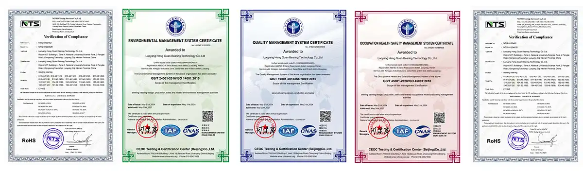
Quality certifications such as ISO9001 can provide evidence of a documented quality management system, but they should be considered together with product-specific inspection and manufacturing information.
Procurement Considerations for Customized Projects
For OEMs and equipment manufacturers, the lowest purchase price is not always the lowest total cost.
A suitable supplier should be evaluated according to technical capability, manufacturing consistency, inspection procedures, communication, lead time, and after-sales support.
For a customized slewing ring, buyers should confirm the following before production:
approved technical drawings;
material requirements;
heat-treatment requirements;
dimensional tolerances;
gear specifications;
mounting-hole arrangement;
sealing requirements;
lubrication requirements;
inspection and acceptance criteria; and
packaging and delivery conditions.
A sample or first-article inspection can also help confirm that the production bearing matches the approved design before larger quantities are released.
Conclusion
A slewing ring works by combining structural load support and controlled rotation in one integrated bearing assembly. Its inner and outer rings, rolling elements, raceways, seals, and gear system each perform a specific function, while the complete assembly transfers axial loads, radial loads, and overturning moments between the rotating and stationary structures.
The integrated gear adds another important function by transmitting torque from a pinion into the rotating ring. Smooth and reliable operation depends on correct raceway geometry, appropriate materials and heat treatment, adequate lubrication, effective sealing, accurate mounting, and proper gear alignment.
For equipment designers and procurement teams, selecting the right slewing ring therefore requires more than comparing outside diameter or catalog load ratings. The complete load case, operating environment, rotation requirements, gear torque, mounting structure, maintenance conditions, and expected service life should all be considered. For customized applications, working with a manufacturer that can provide engineering support, controlled manufacturing, product inspection, and clear technical documentation can reduce design and operational risks while helping the bearing perform consistently throughout its intended service life.
|
|
FAQ
1. How do I determine the correct bearing size for my equipment?
Drive teeth are placed on the inner ring by internal gear slewing bearings. This makes for compact installations that protect the gear mesh from dust, water, and other debris that are common in mining and construction. When you use an external gear version, the teeth are on the outside ring, which makes it easier to inspect and fix. For applications with limited space that need to protect against contamination, internal configurations usually work best.
2. What lubrication intervals extend operational life most effectively?
Ask for thorough information about the building, such as a list of all the machines and systems used, such as CNC machines, grinding machines, and heat treatment systems. Ask for sample inspection reports that show the tolerances and surface finish standards that were met. Third-party facility audits are a reliable way to make sure. Sample orders let you check the accuracy of the measurements, the hardness of the material, and how well it works for your needs before committing to large quantities.
3. Can manufacturers provide custom designs for specialized machinery?
The P0 grade is used in general industrial settings that need standard levels of accuracy. For machines that need to run more smoothly and with tighter tolerances, the P6 grade makes the rotation more accurate. P5 grade is good for precise machines like automation and positioning systems. The P4 grade is the most accurate and is used in aerospace, medical devices, and very accurate measuring equipment. What grade to use depends on the application conditions, such as rotational speeds, load characteristics, and the need for precise positioning.
Partner with Heng Guan for Precision-Engineered Slewing Ring Solutions
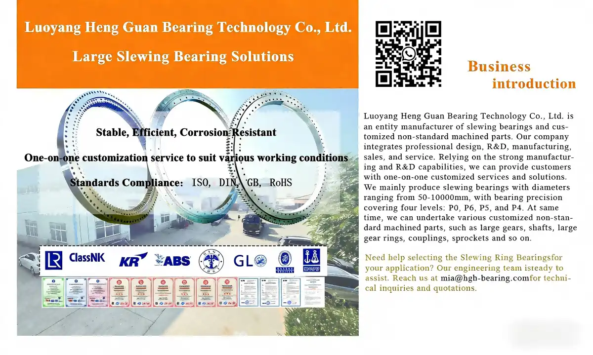
With more than twenty years of experience, Luoyang Heng Guan Bearing Technology makes precision Slewing Rings with diameters ranging from 50mm to 10,000mm using high-quality 42CrMo and 50Mn alloy steels. Our facility is ISO9001-certified and has advanced CNC machining centers and precision grinding equipment. It is run by more than 50 dedicated bearing engineers who make parts with accuracy grades from P0 to P4. We have clients in more than 50 countries in North America, Europe, Asia, and Slewing Ring who work in construction, mining, wind energy, automation, and aerospace. Our engineering team offers custom design optimization for non-standard uses, making sure that it works perfectly with your equipment. Get in touch with us at mia@hgb-bearing.com to talk about your bearing needs with experienced application engineers who know what heavy machinery needs and can help you find the best solutions that balance performance, durability, and cost-effectiveness for your needs.
References
1. Anderson, M. and Williams, R. (2021). Advanced Bearing Technology for Heavy Industry Applications. Industrial Press.
2. Chen, Q. (2020). "Load Distribution Analysis in Multi-Row Slewing Bearings." Journal of Mechanical Engineering Science, 234(18), pp. 3621-3635.
3. Harris, T.A. and Kotzalas, M.N. (2019). Essential Concepts of Bearing Technology, 6th Edition. CRC Press.
4. Houpert, L. (2018). "Contact Mechanics in Rolling Element Bearings." Tribology International, 125, pp. 86-99.
5. Schmidt, H. and Fischer, B. (2022). Slewing Bearings: Design, Manufacturing and Application. Springer.
6. Zhou, Y. and Liu, X. (2020). "Optimized Design Methods for Large-Diameter Slewing Ring Bearings in Wind Turbine Systems." Renewable Energy Engineering, 15(3), pp. 412-428.

WHAT OUR CUSTOMERS SAY
Here is the customer's evaluation of us