




Pinion Gear Shaft vs. Rack: Which Drive System Is Best?
Choosing between a Shaft/pinion-gear-shaft">pinion gear shaft and a rack sounds simple, yet the decision shapes how smoothly, accurately, and efficiently a machine moves. A bad match equals loudness, backlash, premature tooth wear, and unwanted stops. The two elements function as a pair; therefore, the actual difficulty is how to define each one for your application. Heng Guan Bearing assists engineering teams in evaluating choices and selecting pinion gear shafts that match their load, speed, and space needs. Read on to discover how the system works and where each component is most important.
How Does a Pinion Gear Shaft Work With a Rack in a Drive System?
A rack and pinion drive turns rotation into linear motion. Pinion gear shaft: A tiny round gear on a shaft operated by a motor or gearbox. Its teeth engage with a straight-toothed bar called the rack. As the pinion rotates, it pushes the rack, moving a carriage, gate, or machine table in a regulated direction. The journey length is almost endless, since a rack may be assembled end-to-end, and this structure is ideal for long-stroke equipment.
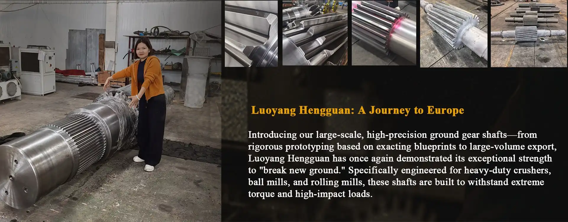
Heng Guan Bearing quality pinion shafts are manufactured with precise tooth profiles and completed journals, so as to provide silent mesh and stable motion. Our pinion gear shaft is one-piece, combining the gear and shaft into one unit, eliminating the alignment difficulties often seen in assembly systems, and saving installation space. We can also match the diameter of the shaft, tooth count, and keyway to your motor and bearing arrangement, giving you a drive that fits from the first installation.
Technical Specifications
| Parameter | Specification |
|---|---|
| Shaft Diameter | φ100 mm – φ1000 mm |
| Total Length | 100 mm – 3000 mm |
| Gear Module | M3 – M20 (customizable) |
| Base Material | 42CrMo, 20CrMnTi, 40Cr alloy steel |
| Core Hardness | HRC 28–32 (after heat treatment) |
| Tooth Surface Hardness | HRC 58–62 (after carburizing) |
| Gear Accuracy Grade | GB 5–6 (ISO equivalent) |
| Connection Types | Keyway, spline, flange |
| Tooth Profile Options | Spur, helical, bevel |
Pinion Gear Shaft vs. Rack: Key Differences in Design and Function
The two pieces function together, but have separate responsibilities. The driving member is the pinion gear shaft, which rotates, delivers torque, withstands bending, and runs true in its bearings. The rack is either a fixed or a traveling piece that provides the long straight route that controls travel. Pinion shafts are commonly composed of alloy steel, heat-treated to provide the teeth with good surface hardness. Racks are created in modules and lengths to meet the stroke.
Heng Guan Bearing provides custom-designed pinion shafts according to size and construction, allowing designers to optimize strength, weight, and cost. Our shafts have carburized tooth surfaces for wear and contact fatigue resistance, fillet shoulder transitions to prevent stress concentration, and CNC-ground bearing seats with a concentricity kept within 0.01 mm. Shafts fit your drivetrain without adapters via keyway (DIN or ANSI), involute or custom spline, or flange connections. The key changes are shown in the table below.
| Feature | Pinion Gear Shaft | Rack |
|---|---|---|
| Motion | Rotating | Linear |
| Main role | Transmits torque | Provides travel path |
| Typical material | Heat-treated alloy steel (42CrMo, 20CrMnTi, 40Cr) | Hardened steel |
| Tooth surface | Carburized, HRC 58–62 | Hardened to suit the stroke and load |
| Customization | Diameter, teeth, keyway, spline, flange | Length, module, mounting |
Which Drive System Offers Better Load Capacity, Speed, and Precision?
Performance relies on the definition of the pair. The bigger modules and harder teeth on the pinion gear shaft and rack also spread the force across a broader contact area to handle huge loads with great capacity for gantries, presses, and lifting equipment. The ground teeth and exact shaft polish enable smooth, high-speed travel with minimum vibration for speed. In automation and machine tools, stringent teeth tolerances and preloaded or split-pinion arrangements are used for precision positioning.
We produce gear shafts to GB 5-6 precision (ISO equivalent) and can fine-tune our pinion shafts to accentuate whatever characteristic your project requires most. The robust core at HRC 28-32 provides shock absorption, and the hard surface of the tooth is wear-resistant. One shaft can take impact as well as lengthy duty cycles. If you want advice on the right balance, send your load, speed, and travel data to mia@hgb-bearing.com, and our engineers will recommend a suitable configuration. The table below gives a quick guide.
| Priority | Recommended Approach | Typical Specification |
|---|---|---|
| High load | Larger module, hardened teeth | Module up to M20, tooth surface HRC 58–62 |
| High speed | Ground teeth, fine shaft finish | CNC-ground bearing seats, concentricity within 0.01 mm |
| High precision | Tight tolerance, preloaded pinion | GB 5–6 accuracy, shaft runout at bearing seats ≤ 0.02 mm |
Industrial Applications and Maintenance Tips for Reliable Rack-and-Pinion Drives
Heng Guan Bearing products are already trusted in construction, mining, port, lifting, automation, and many other sectors, including rack and pinion driving applications. Typical usage includes gantry cranes, sliding gates, CNC machines, and material handling lines. Our pinion shafts are also used in rolling plants, gearboxes, reducers, wind turbine gearboxes, and marine motors.
A few easy practices maintain any pinion gear shaft in good working condition: proper lubrication at regular intervals, verify alignment and backlash during frequent inspections, maintain the rack clean, and tighten fasteners on a timetable. With these procedures, pinion shafts provide extended, consistent service and fewer interruptions. The following timetable reflects our suggested practice.
| Item | Action Required |
|---|---|
| Lubrication | Follow the host machine manufacturer's oil type and change intervals. |
| Routine inspection | Check for abnormal noise or vibration, and verify alignment and backlash. |
| Tooth wear | Measure tooth thickness periodically; replace when wear exceeds 15% of the original dimension. |
| First operation | Run at reduced load initially and monitor temperature and vibration. |
| Storage | Apply anti-corrosion coating and store in climate-controlled conditions. |
We have a client-focused staff providing unique design and flexible manufacturing. We manufacture using your 2D or 3D designs or samples. If you don't have drawings, we can reverse engineer. We do single items as well as huge volume orders. All orders include material test reports and dimensional certifications with spectrum analysis, ultrasonic fault identification, CMM dimensional checks, and tooth profile inspection. Standard parts are about 3-4 weeks, and bespoke parts are around 6-8 weeks. Each drive system is designed for your working requirements and provided with reliable technical assistance.
Conclusion
A pinion gear shaft and rack are preferable as a matched pair, each selected for load, speed, and accuracy. Heng Guan Bearing’s customized pinion shafts allow you to construct a dependable, long-lasting drive for any industrial application.
FAQ
Q: What does a pinion gear shaft do?
A: It turns rotation into linear motion by meshing with a rack.
Q: Can pinion shafts be customized?
A: Yes. Diameter, teeth, keyway, spline, and flange connections can be adjusted to your needs, and we can build from 2D or 3D drawings or samples.
Q: Which system handles heavier loads?
A: Larger modules and hardened teeth on both parts increase load capacity.
Q: How do I keep a rack-and-pinion drive reliable?
A: Lubricate regularly, check backlash and alignment, and keep the rack clean.
Q: Which industries use these drives?
A: Construction, mining, port, lifting, and automation.
Q: What is the typical delivery time?
A: Standard parts take about 3–4 weeks. Custom parts take about 6–8 weeks, depending on complexity and production schedule.
Ready to Upgrade Your Drive? Contact Us Today
Contact Heng Guan Bearing for a tailored solution:
- Shaft diameters from φ100 mm to φ1000 mm, modules M3–M20
- ISO 9001-certified production, custom sizing, and material options
- Engineering support for drive selection, drawings, and reverse engineering
- Proven solutions for gantries, gearboxes, CNC machines, and material handling lines
Send your drawings and requirements to mia@hgb-bearing.com, and our engineers will recommend the right pinion gear shaft for your project. Let's build a smoother, stronger drive together.
References
1. Budynas, R. G., & Nisbett, J. K. (2014). Shigley's Mechanical Engineering Design. McGraw-Hill.
2. Norton, R. L. (2020). Machine Design: An Integrated Approach. Pearson.
3. Hamrock, B. J., Schmid, S. R., & Jacobson, B. O. (2004). Fundamentals of Machine Elements. McGraw-Hill.
4. Dudley, D. W. (1984). Handbook of Practical Gear Design. McGraw-Hill.
5. American Gear Manufacturers Association. (2016). ANSI/AGMA 2001-D04: Fundamental Rating Factors and Calculation Methods for Involute Spur and Helical Gear Teeth.
6. Harris, T. A., & Kotzalas, M. N. (2006). Essential Concepts of Bearing Technology. CRC Press.

WHAT OUR CUSTOMERS SAY
Here is the customer's evaluation of us