




What Should Buyers Check Before Ordering a Pinion Shaft?
The Shaft/pinion-shaft">pinion shaft is the small driving gear and shaft that transmits power through your gearbox; thus, one careless order might lead to weeks of downtime. At Luoyang Heng Guan Bearing Technology Co., Ltd. (LYHGB), we believe that it is best for customers to examine four things early: material, accuracy, compatibility, and supplier capabilities. Get those four right, and the shaft you get drops into the housing and meshes nicely with the mating gear and remains silent for years. One slip and you’re stuck with loudness, premature teeth damage, and an unscheduled teardown.
Which Material and Heat Treatment Are Best for Your Pinion Shaft?
And start with the steel. That's going to determine how long your pinion shaft will endure under strain. Popular alternatives include 20CrMnTi, 42CrMo, and 40Cr, with bespoke grades available when your duty cycle needs it. Carburized teeth for heavy-duty drives may have a surface hardness of HRC 58–62, while the core remains robust at HRC 28–32 after quenching and tempering. The dual-hardness construction provides wear resistance and shock tolerance in one component. The casing resists contact stress and pitting, the ductile core absorbs bending loads, and the impact spikes crushers and rolling mill stands supply every shift.
At Heng Guan Bearing, each pinion shaft is machined from a single forging so that the gear and shaft are one robust, concentric body. There is no weld seam, no shrink fit, no keyed-on gear to pull loose under reverse force. That is why integrally manufactured devices outlive assembled ones in high-shock usage. Before you validate a grade, ask each supplier for chemical composition reports and hardness gradient data; a hardness number on the surface tells you nothing about how fast the case becomes a soft core. Next, let’s explore how to check the numbers on your design.
| Steel Grade | Heat Treatment | Surface / Core Hardness | Typical Duty |
|---|---|---|---|
| 20CrMnTi | Carburizing + quenching | HRC 58–62 / HRC 28–32 | High-shock mining and crusher drives |
| 42CrMo | Quenching + tempering, nitriding optional | HRC 50–56 / HRC 28–32 | Rolling mill and heavy gearbox service |
| 40Cr | Quenching + tempering | HRC 45–52 / HRC 25–30 | General industrial reducers |
| Customer-specified | Matched to drawing | Per specification | Marine, hydro, and special environments |
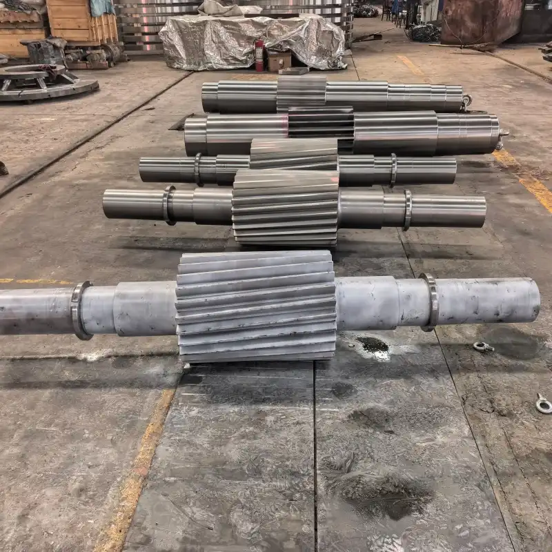
How Do You Verify Pinion Shaft Dimensions, Tolerances, and Gear Accuracy?
Once the material has settled, confirm that the pinion shaft matches the sketch and the final tolerance. Standard units are available in diameters from 50 mm to 500 mm and lengths from 300 mm to 3,000 mm, with gear modules from M3 to M20 and unit weights from 5 kg to 500 kg. Tooth accuracy is usually GB 5-6 or ISO 1328 Class 6-7, and bearing seats and teeth are precisely honed for smooth rotation.
Request CMM reports for tooth geometry and ultrasonic and magnetic particle inspection reports for crucial locations. Ultrasonic examination of the forging detects internal inclusions before any machining time is required. Magnetic particle inspection detects surface and near-surface fractures at fillets and shoulder transitions where stress accumulates. Check runout after delivery to make sure it stays below 0.02 mm as it spins – the dial indicator goes on the bearing seats and the gear blank, and take readings at a few angles rather than just one, so you know the pinion shaft is tracking true throughout an entire revolution, not just where it happens to be sitting.
LYHGB performs raw material chemical analysis, forging ultrasonic defect identification, comprehensive CMM tooth geometry inspection, surface and core hardness gradient verification, and magnetic particle inspection on crucial sections as routine stages on every batch. The main checkpoints are summarized in the table below.
| Checkpoint | Typical Range | Why It Matters |
|---|---|---|
| Shaft diameter | 50–500 mm (custom to 800 mm) | Bearing seat and housing fit |
| Overall length | 300–3,000 mm (custom to 6,000 mm) | Bearing span and shaft deflection |
| Gear module | M3–M20 | Tooth strength and load transfer |
| Tooth accuracy | GB 5-6 / ISO 1328 Class 6-7 | Noise, vibration, and load distribution |
| Backlash | 0.2–0.5 mm by module | Thermal growth and positioning repeatability |
| Installed runout | Within 0.02 mm | Seal life and even tooth contact |
Pinion Shaft Compatibility: Checking Gear Geometry, Splines, and Fitment
Compare gear geometry first — a pinion shaft is only right if it suits the rest of your gearbox. Spur, helical, and bevel tooth profiles are all available, so before purchase, check the module, pressure angle, and center distance of your matching gear. The most typical issue we encounter in retrofitting is a mismatch in pressure angle. The teeth seem similar on a model; they assemble without complaint, and then they scream under load because the contact pattern never forms correctly.
Then, check the connection type. Easier to adapt using keyway, spline, flange, or bespoke connections to existing equipment, cutting installation time. Plan for normal backlash of 0.2 mm - 0.5 mm depending on module size. Remember that backlash diminishes as the gearbox heats up — a mesh that seems tight on the bench might seize at operational temperature. If you just have a worn sample rather than a design, our engineers can reverse-engineer it using measurements and tooth-contact tests, and then create a bespoke tooth profile to fit your correct specification even without 3D blueprints. Send your parameters to mia@hgb-bearing.com, and the Heng Guan Bearing team will help you check fitment before production starts. The table below lists the standard specification set we build to.
| Parameter | Specification |
|---|---|
| Shaft diameter | φ50 mm – φ500 mm (custom up to φ800 mm) |
| Overall length | 300 mm – 3,000 mm (custom up to 6,000 mm) |
| Gear module | M3 – M20 |
| Unit weight | 5 kg – 500 kg |
| Base material | 20CrMnTi, 42CrMo, 40Cr, or per customer specification |
| Tooth surface hardness | HRC 58–62 after carburizing |
| Core hardness | HRC 28–32 after quenching and tempering |
| Tooth accuracy grade | GB 5-6 / ISO 1328 Class 6-7 |
| Tooth profile options | Spur, helical, bevel |
| Connection type | Keyway, spline, flange, or custom interface |
| Typical backlash | 0.2 mm – 0.5 mm depending on module size |
| Installed runout | Within 0.02 mm during rotation |
| Inspection routine | Chemical analysis, UT, CMM, hardness gradient, magnetic particle |
| Certification | ISO 9001:2015, RoHS compliant |
| Packaging | Wooden crate, sturdy frame, or composite reinforced |
| Lead time | 4–6 weeks standard; 8–10 weeks for complex designs |
How Can You Compare Pinion Shaft Manufacturers for Quality, Cost, and Lead Time?
When comparing pinion shaft manufacturers, look beyond the listed price. Heng Guan Bearing, a Luoyang-based company with more than 20 years of machining expertise, has ISO 9001:2015-certified manufacturing and modern testing equipment. Ask each supplier for inspection reports, bespoke design assistance, and export experience. Ask to see the real test certifications, not a general declaration of compliance.
Packaging is also important because hardwood boxes, solid frames, or composite reinforced packaging safeguard your shafts in transportation; a 400 kg shaft with a ground bearing seat is worthless if it has been rubbing against bare steel for three weeks at sea. Another important issue is lead time. Standard adaptations are normally 4-6 weeks after drawing approval, but intricate designs or unusual materials might take 8-10 weeks. A supplier who estimates three weeks for a carburized, ground, CMM-verified pinion shaft is generally omitting a step, and it’s nearly always the stage you need the most. Score your choices against the table below, and you will soon know which provider delivers the greatest overall value.
| Factor | What to Ask | Heng Guan Bearing Answer |
|---|---|---|
| Quality | Material and inspection reports | Chemical analysis, UT, CMM tooth geometry, hardness gradient, MT |
| Cost | Price including packaging and freight | Quoted with export packaging and freight terms stated separately |
| Lead time | Realistic schedule after drawing approval | 4–6 weeks standard; 8–10 weeks complex |
| Support | Reverse engineering and technical help | Reverse engineering from samples and measurements, no 3D drawing needed |
| Traceability | Heat number and certificate retention | Heat-linked material certificates retained per order |
Conclusion
Selecting the proper pinion shaft is a matter of 4 checks: adequate material and heat treatment, checked tolerances, confirmed fitting, and a reliable source. Follow this checklist, and you decrease risk, safeguard uptime, and assure extended service life. This slips a shaft right into the housing, operates silently at rated torque, and offers maintenance crews a service interval, not a recurrent issue. Heng Guan Bearing is here to help your next project.
FAQ
Q: Which materials are available?
A: 20CrMnTi, 42CrMo, 40Cr, or custom materials on request.
Q: What size range do you cover?
A: Standard diameters of 50–500 mm and lengths of 300–3,000 mm, with custom units machined up to φ800 mm and 6,000 mm.
Q: What tooth accuracy can I expect?
A: Typically GB 5-6 or ISO 1328 Class 6-7, verified by CMM inspection.
Q: Can you make a shaft without a drawing?
A: Yes. Our engineers can reverse-engineer a sample from measurements and tooth-contact tests.
Q: What is the usual lead time?
A: Standard customizations take about 4–6 weeks after drawing approval; complex designs or special materials need 8–10 weeks.
Ready to Order Your Pinion Shaft?
Contact Heng Guan Bearing today at mia@hgb-bearing.com with your drawings, size, or application. Our engineers will review your requirements, recommend the right material for your pinion shaft, and send a tailored quote promptly. Let us build reliable power transmission together.
References
1. International Organization for Standardization. ISO 1328-1: Cylindrical Gears – ISO System of Flank Tolerance Classification, Part 1. 2013.
2. International Organization for Standardization. ISO 6336-1: Calculation of Load Capacity of Spur and Helical Gears, Part 1. 2019.
3. American Gear Manufacturers Association. ANSI/AGMA 2001-D04: Fundamental Rating Factors and Calculation Methods for Involute Spur and Helical Gear Teeth. 2004.
4. Budynas, R. G., & Nisbett, J. K. Shigley's Mechanical Engineering Design. McGraw-Hill Education.
5. Davis, J. R. (Ed.). Gear Materials, Properties, and Manufacture. ASM International, 2005.
6. Radzevich, S. P. Dudley's Handbook of Practical Gear Design and Manufacture. CRC Press.

WHAT OUR CUSTOMERS SAY
Here is the customer's evaluation of us