




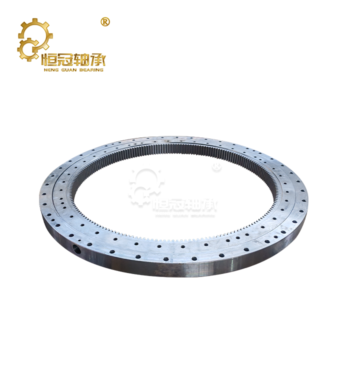
RD 900 slewing bearing
Number of rows: 3
Key selling point: Load separation—each row handles only one type of force
DL range: 1,250–6,735 mm
Maximum weight: 11.3 tonnes
H range: 132–268 mm
Unique advantage: Radial forces do not affect the critical load curve
The RD 900 represents the ultimate evolution of slewing bearing design. The three roller rows each perform a specific function: the upper row of axial rollers handles downward pressure, the lower row of axial rollers handles upward tension, and the middle row of radial rollers handles lateral forces.
Highest load density among slewing bearing types: For the same mounting diameter, the load-bearing capacity of the RD 900 far exceeds that of any ball bearing or hybrid bearing.
- Product Description
RD 900 Slewing Bearing – Triple-Row Roller Design for Ultra-Heavy Industrial Applications
The RD 900 Slewing Bearing represents the pinnacle of load-carrying capability in rotary support engineering. Built on the principle of load-path separation, this three-row roller bearing assigns each force direction to a dedicated roller row: the upper axial row handles compressive vertical loads, the lower axial row counteracts tensile lifting forces, and the independent radial row manages horizontal side loads without derating axial capacity. Available across five roller size classes spanning DL 1,250–6,735 mm, height 132–268 mm, and weights up to 11,300 kg, the product delivers typical load capacities from 116.7 kN (Class 20) to 847.2 kN (Class 50), making it the preferred solution for offshore pedestal cranes, tunnel boring machine main bearings, and continuous casting ladle turrets.
Technical Specifications
The RD 900 slewing bearing is manufactured in five distinct engineering classes, each optimized for specific load regimes and operating environments:
Roller Class | External Gear (191) | Internal Gear (192) | DL Range (mm) | Height H (mm) | Typical Load Fn (kN) | Max Load Fmax (kN) |
Class 20 | 5 models | 5 models | 1,250–2,000 | 132 | 116.7–155.6 | 233.4–311.2 |
Class 25 | 5 models | 5 models | 1,800–2,800 | 147 | 162.7–203.4 | 325.4–406.8 |
Class 32 | 6 models | 6 models | 2,240–4,000 | 181 | 217.6–265.9 | 435.2–531.8 |
Class 40 | 5 models | 5 models | 2,800–4,500 | 220 | 295.7–354.8 | 591.4–709.6 |
Class 50 | 8 models | 8 models | 3,150–6,735 | 268 | 423.6 | 847.2 |
Total available models: 58 (29 external gear + 29 internal gear configurations)
Each class represents a fully engineered design tier with independently optimized roller geometry, raceway contact angles, and ring cross-sections—not simply scaled dimensions.
Core Engineering Principles
Three Independent Roller Rows: Load-Path Separation
The defining advantage of the RD 900 is its dedicated load-path architecture. Ball bearings and double-row designs force all load types—axial compression, axial tension, radial—through shared contact paths. This creates capacity derating when multiple loads act simultaneously. The RD 900 eliminates this compromise:
· Upper axial row: Sized and preloaded for compressive vertical loads from superstructure deadweight and payload
· Lower axial row: Handles tensile forces generated on the tension side during tilting moments
· Radial row: Positioned centrally with geometry optimized exclusively for horizontal side loads
No row derates another. No shared contact path limits total capacity. The result is the highest load density per unit bearing diameter available in slewing ring engineering.
Radial Load Decoupling: Side Forces Do Not Reduce Vertical Capacity
In conventional single-row and double-row bearings, radial forces share the rolling element contact path with axial loads. As radial load increases, remaining axial capacity decreases—a phenomenon known as load interaction. The RD 900's independent radial roller row absorbs lateral forces without affecting the axial rows' rated capacity. Your vertical load safety margin remains intact regardless of side force magnitude.
This decoupling is critical where side loads are unpredictable:
· Wave-induced vessel motion on offshore crane slewing bearing triple-row installations
· Gusting crosswinds on mobile harbour cranes at maximum outreach
· Uneven rock face contact generating fluctuating radial loads on tunnel boring machine main bearing cutterheads
In these scenarios, the bearing's primary safety consideration—vertical load capacity—is never compromised by lateral forces.
Five Size Classes for Graduated Heavy-Duty Capacity
Each roller class represents a distinct engineering tier:
· Class 20: DL 1,250–2,000 mm, H 132 mm, 539–912 kg — Mid-size mobile cranes, material handlers
· Class 25: DL 1,800–2,800 mm, H 147 mm, 1,101–1,785 kg — Heavy excavators, ship unloader slewing bearing installations, mid-size ladle turrets
· Class 32: DL 2,240–4,000 mm, H 181 mm, 1,975–3,752 kg — Mobile harbour cranes, offshore deck cranes, large ladle turrets
· Class 40: DL 2,800–4,500 mm, H 220 mm, 3,213–5,410 kg — Steel mill ladle turrets, heavy lift crane slewing ring triple-row applications, large draglines
· Class 50: DL 3,150–6,735 mm, H 268 mm, 5,128–11,330 kg — Tunnel boring machine main bearing assemblies, ultra-class marine heavy-lift cranes, mining dragline slewing bearing systems
Roller length-to-diameter ratios, raceway contact angles, bolt patterns, and ring cross-sections are individually engineered for each class's load regime. This prevents both under-engineering and unnecessary cost.
All Three Gear Configurations
Your drive architecture determines gear type:
· 190 prefix (no gear): For external drive mechanisms—hydraulic cylinders, multiple pinions on separate rings, friction drives
· 191 prefix (external gear): Precision-hobbed teeth on the outer ring for standard pinion-driven slewing drives. Most common for cranes and excavators.
· 192 prefix (internal gear): Teeth cut on the inner ring for compact drive integration. Preferred for ladle turret slewing ring three-row installations (drive protected from radiant heat), TBMs (multiple pinions for distributed torque), and offshore cranes (drive mechanism housed within the pedestal for weather protection)
Mission-Critical Manufacturing & Quality Assurance
Every RD 900 bearing is built for zero-failure operational profiles:
· Ring material: Forged 42CrMo alloy steel, quenched and tempered to 280–320 HB core hardness, with three raceway surfaces induction-hardened to HRC 55–62
· Roller material: Vacuum-degassed GCr15 bearing steel with controlled inclusion ratings. Rollers matched within sub-micron tolerance bands per row.
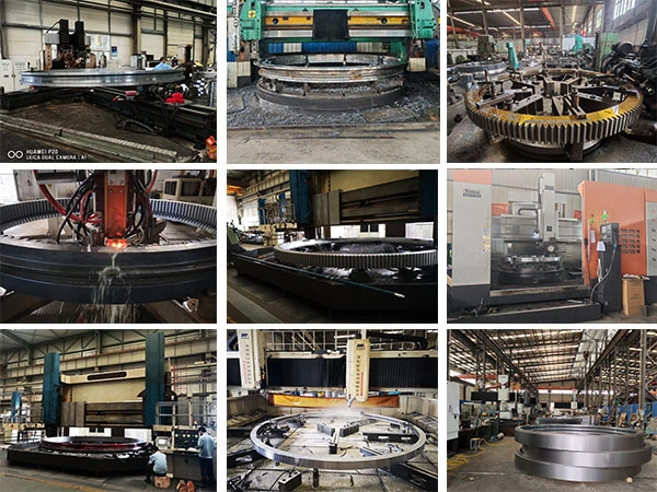
· Raceway grinding: Three independent profiles ground in a single setup to maintain geometric relationships. Profilometer-verified surface finish.
· Inspection: 100% CMM dimensional verification. Raceway hardness mapping. Rotational torque measured at multiple positions.
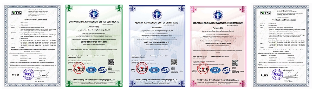
· Documentation: Material certificates with heat number traceability, heat treatment records, complete dimensional inspection reports provided as standard
Industrial Applications
Offshore Heavy-Lift Cranes
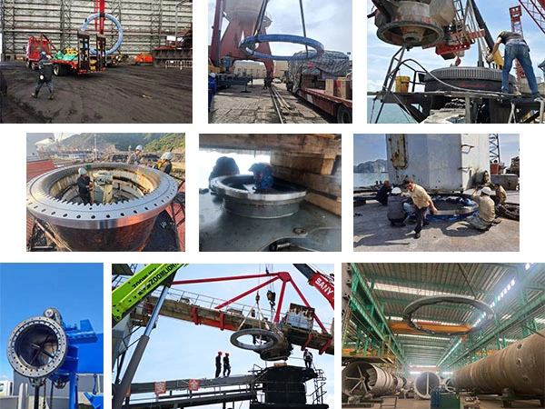
Offshore platform pedestal cranes and floating crane vessels handling subsea equipment, risers, and wind turbine components generate tilting moments that only a three-row roller bearing can accommodate within pedestal diameter constraints. RD 900 bearings in the 2,500–5,000 mm DL range, with Class 32–50 rollers, are specified for these installations.
The radial load decoupling is particularly valuable offshore. Wave-induced vessel motion imposes dynamic lateral forces that, in other bearing types, would consume axial capacity needed for the suspended load. In the RD 900, the dedicated radial row absorbs these forces without derating the axial rows—your vertical load capacity remains unchanged regardless of sea state.
Internal gear configurations (192 prefix) house the slewing drive mechanism within the pedestal column for protection from wave impact. Enhanced corrosion protection packages include thermal spray coatings, fluoroelastomer seals, and stainless steel ancillaries. Full material traceability and inspection documentation support classification society certification.
Tunnel Boring Machines
TBM main bearings—with diameters up to 6.7 meters and weights exceeding 11 tons—must transmit thrust loads often exceeding 10,000 kN through solid rock for kilometers without replacement until breakthrough. RD 900 bearings in the 3,150–6,735 mm DL range, with Class 50 rollers, provide the ultimate load capacity at these massive diameters.
The internal gear variant (192 prefix) is standard for TBM installations, with 8 to 16 pinions arranged around the inner ring, each driven by an independent electric motor. This distributed drive architecture provides both the enormous torque required for hard-rock cutting and built-in redundancy—loss of one drive unit does not immobilize the machine.
Radial load decoupling is critical where uneven rock face contact generates fluctuating radial loads. The independent radial roller row handles these variable side forces without affecting axial thrust capacity—ensuring full forward thrust regardless of face conditions.
Steel Mill Ladle Turrets
Continuous casting ladle turrets subject slewing bearings to extreme combinations of load, temperature, and operating conditions. A single bearing must support two ladles—each weighing 100 to 350 tons when filled with molten steel at temperatures exceeding 1,500°C—on a rotating arm that cycles one ladle into casting position while simultaneously receiving the next filled ladle.
RD 900 bearings in the 2,240–4,500 mm DL range, with Class 32–40 rollers, are specified for ladle turret applications. The three-row design's tilting moment capacity is essential: the ladle arm creates an enormous tilting moment when one full ladle is raised to casting position at maximum arm radius while the opposite arm receives the next ladle. The lower axial roller row is specifically engineered to handle the tension-side lifting forces generated by this asymmetric loading.
Internal gear configurations (192 prefix) house the slewing drive within the turret column—protected from radiant heat and airborne mill scale. High-temperature grease (rated to 200°C continuous) and enhanced labyrinth sealing with purged air connections are standard. Bolt preload monitoring provisions allow maintenance teams to verify fastener tension during scheduled outages without disassembly.
Certification
FAQ
Q: What makes the RD 900 different from double-row roller bearings?
A: The RD 900 uses three independent roller rows—one for compression, one for tension, and one for radial loads. Double-row bearings share load paths, which reduces capacity when multiple load types act simultaneously. The RD 900's load-path separation eliminates this derating.
Q: Can the RD 900 handle combined high radial and axial loads?
A: Yes. The dedicated radial roller row absorbs lateral forces independently. Your axial load capacity remains at full rated value regardless of radial force magnitude within the bearing's design envelope.
Q: What is the delivery time?
A: In-stock products ship within 7–15 days. Custom configurations take 4–6 weeks, depending on complexity.
Contact Us
For the RD 900 slewing bearing, if you need selection assistance, custom configuration requirements, or technical consultation for your specific application, reach out to our engineering team at mia@hgb-bearing.com. Download detailed dimensional drawings, request material certificates, or discuss your project requirements directly with our specialists.

WHAT OUR CUSTOMERS SAY
Here is the customer's evaluation of us